Eureka AIR delivers breakthrough ideas for toughest innovation challenges, trusted by R&D personnel around the world.

Method and device for reading a physical characteristic on an object

Active Publication Date: 2015-03-17
ADVANCED TRACK TRACE
View PDF13 Cites 9 Cited by
  • Summary
  • Abstract
  • Description
  • Claims
  • Application Information

AI Technical Summary

Benefits of technology

The present invention provides a way to capture physical characteristics of objects using low-end digital image capture methods such as flatbed scanners and digital cameras. The invention can stabilize and standardize the positioning of the area where physical characteristics are read, while also reducing the number of coefficients to identify an object and storing it more efficiently. Additionally, a hashing function is applied to the physical characteristic to allow for quicker identification. Overall, the invention allows for efficient and accurate capture of physical characteristics of objects.

Problems solved by technology

There is currently no known physical process that can reproduce this random structure.
Thus, the majority of objects naturally possess characteristics that allow them to be characterized in a manner that is unique, not reproducible, and negligibly affected by time and wear.
It is noted that the database search can be expensive and that it must be optimized if a large number of objects are stored.
It is noted that the capture of imprints is very sensitive to positioning problems; a positioning error of just one millimeter can invalidate the reading.
These techniques have disadvantages.
Their implementation is usually expensive and fragile.
Consequently, these techniques are difficult to exploit.
Furthermore, they significantly complicate the imprint registration phase.
The complexity and cost of this phase is thus a major obstacle to the adoption of this technology.
However, exploitation of the technology is limited by the cost (and hence scarcity), size and weight of reading devices, making “on-site” reading difficult if not impossible.
In the context of trademark protection, however, the positions of the processed areas would have to be known for a very large number of products; this is not possible, even for an inspector or customs officer trained for this purpose.
In addition, these techniques have a very low tolerance to positioning errors: a shift of one millimeter or a rotation of one degree may be enough to cause the extracted characteristics not to correspond to the characteristics measured at the time of registration.
Reading is therefore a very delicate procedure that should primarily be conducted in the laboratory.
Consequently, these technologies are still mainly limited to forensic use, which reduces their value considerably.
However, the difficulties of positioning the object are not addressed in that document.
As mentioned earlier, however, this is not possible in the field of trademark and design protection, as this position would have to be known for a very large number of objects.
However, the capture must always be precisely adjusted to this reference point, and the positioning problem is not solved.
It must be noted that positioning problems may also apply when reading an invisible mark applied to a product.
One or more images covering only a fraction of the surface of the product are therefore generated, raising the problem of determining the areas of the image to be captured.

Method used

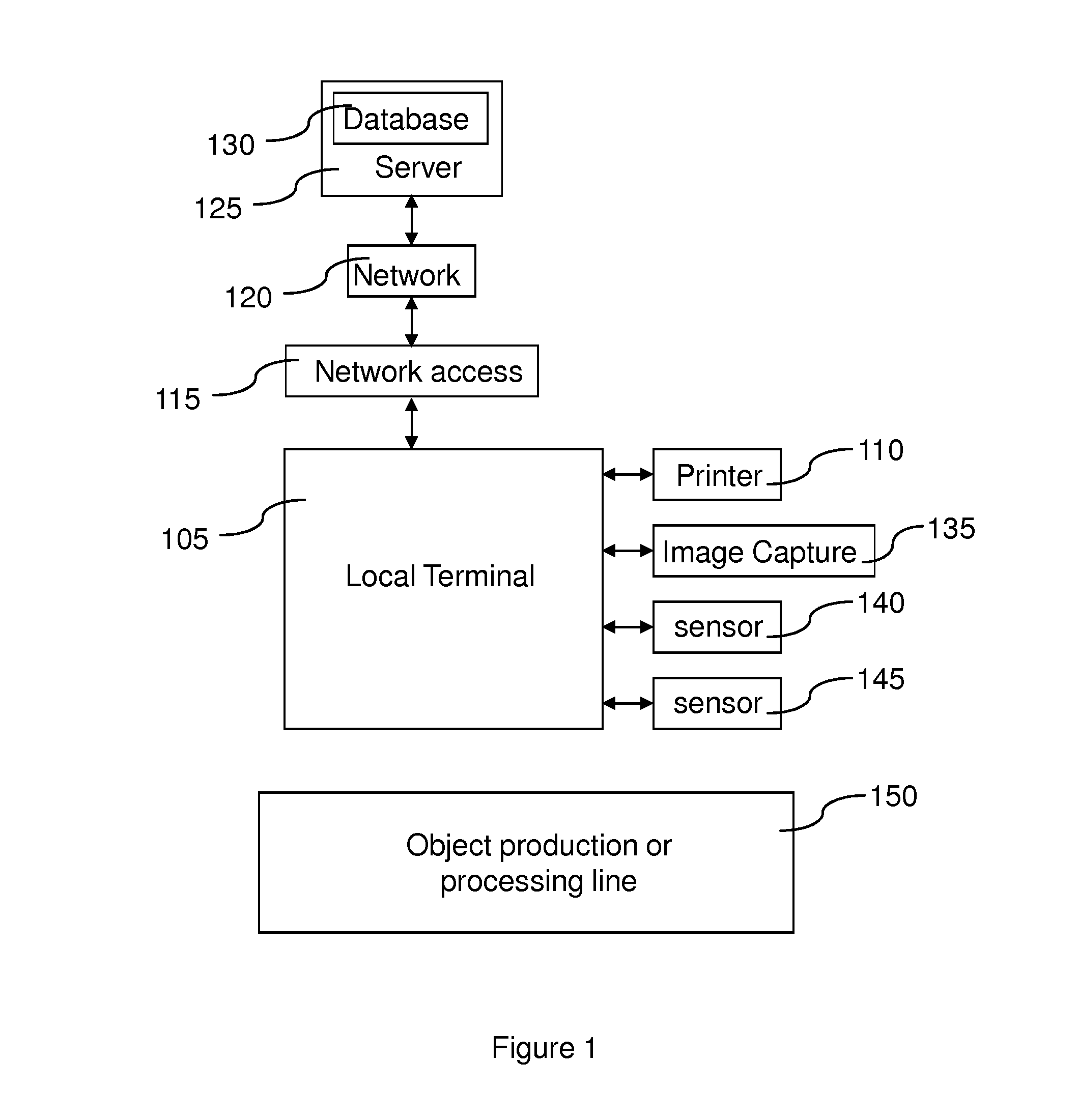

Image

  • Method and device for reading a physical characteristic on an object
  • Method and device for reading a physical characteristic on an object
  • Method and device for reading a physical characteristic on an object

Examples


first embodiment

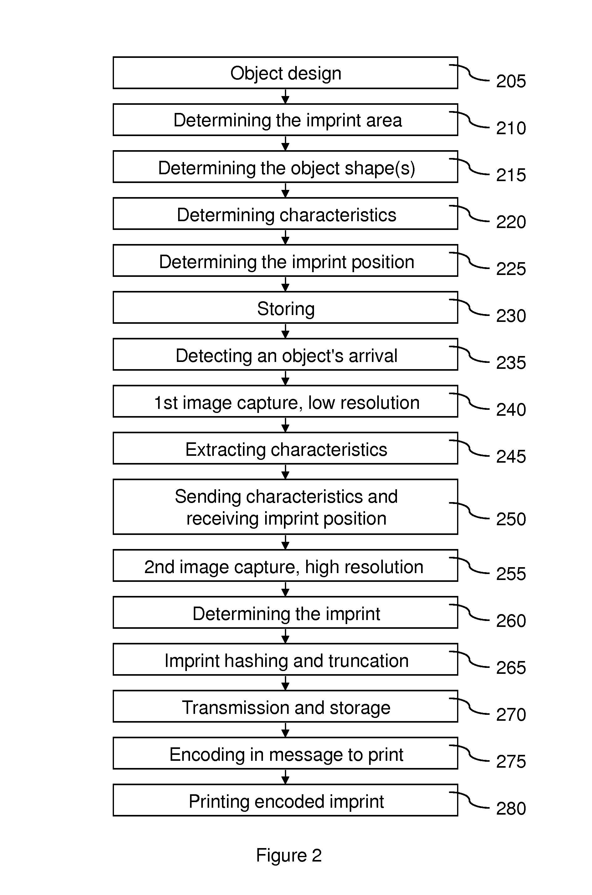
[0060]The description of the operation of the method of reading object imprints that is the subject of the present invention follows, with reference to the steps illustrated in FIG. 2.

[0061]In a step 205, an object type is designed, for example a new package.

[0062]In a step 210, each position will be determined of an area on the object from which an imprint or information representing the position of such an area will be read.

[0063]In a step 215, the shape or shapes that the object may take in an image taken by the image sensor 135 is determined (e.g. the front or back side of a package can be seen before folding).

[0064]In a step 220, the characteristic points or lines of the object, in the shapes it may take, are determined.

[0065]In a step 225, the position of each said area within each shape seen is determined.

[0066]In a step 230, the result of steps 215 to 225 is stored, for example in the database 130, for each type of object.

[0067]In a step 235, the arrival of the object near o...

second embodiment

[0091]The description of the operation of the method of reading object imprints that is the subject of the present invention follows, with reference to the steps illustrated in FIG. 3.

[0092]In a step 305, said object is put in motion, for example on a conveyor with a digital image sensor, optical position sensors and a computer for controlling, processing and communicating with the server.

[0093]In a step 310, the arrival of the object near or in the image sensor's field of vision is detected. The speed of the object is then measured and, depending on this speed and the distance between the location of detection of the object's arrival and the end of the sensor's field of vision, the duration to wait before capturing the image of the object is determined. There then follows a wait for this duration.

[0094]In a step 315, a first image of the object is captured, with a first resolution.

[0095]In a step 320, image processing of the object is performed to extract the characteristic contour...

third embodiment

[0105]In the third embodiment, shown in FIG. 4, the geometric shape of the object is used to locate the position of the imprint:[0106]in a step 405, at least a large part of the back surface of the packaging is captured at low resolution,[0107]in a step 410, the boundaries of the object are determined and optionally the object's reference point,[0108]in a step 415, based on the object's boundaries and, optionally on reference points, the database is searched for the object's geometric shape,[0109]in a step 420, based on the object's geometric shape, the associated stored position of the imprint area is determined,[0110]in a step 425, the actual position of the imprint area within the scanner's capture field and the image's angle of rotation are calculated,[0111]in a step 430, the imprint area thus determined is captured at high resolution,[0112]in a step 435, optionally, a rotation inverted in relation to the rotation determined in step 425 is performed,[0113]in a step 440, the impr...


PUM


Abstract

A method for reading a physical characteristic on an object includes:a step (240, 315, 405) of capturing a first image of at least a portion of the object with a first resolution;a step (245, 320, 415, 420) of determining the position of an area of the object to be processed, according to the first image;a step (255, 330, 430) of capturing a second image of the area of the object to be processed, with a second resolution higher than the first resolution; anda step (260, 335, 440) of determining the physical characteristic based on the second image. In some embodiments, there is, in addition, a step of marking the object with a mark bearing information representative of at least a portion of the physical characteristic.

Description

BACKGROUND OF THE INVENTION[0001]The present invention relates to a method and a device for reading a physical characteristic on an object.[0002]It aims in particular to solve counterfeit and gray market problems and generally, a problem of identification and / or authentication of any object, particularly a product, a document, for example an identification document, packaging or banknotes. More specifically, the present invention envisages a system to facilitate the registration of an object's unitary imprint during the object's manufacturing phase and to facilitate the extraction of the imprint during the object's identity and authenticity verification phase.DESCRIPTION OF THE RELATED ART[0003]Fibrous objects (paper, cardboard) and the majority of metal, plastic, coated paper or other objects have, at the microscopic level, a structure random in nature. In the same way as biometric techniques that use the unique structures forming the hand or iris imprints for identification or ide...

Claims


Application Information

Patent Timeline
IPC IPC(8): G06K9/36G06V30/224G07D7/12G07D7/20
CPCG06K9/3216G06K9/00577G06K9/6857G07D7/2033G07D7/12G07D7/2008G06K2009/0059G06V20/95G06V20/80G06V10/245G06V30/2504G06K19/06G06V30/224
Inventor SAGAN, ZBIGNIEWFOUCOU, ALAINMASSICOT, JEAN-PIERRE
Owner ADVANCED TRACK TRACE
Why Eureka
Eureka Blog
Learn More