Earphone arrangements

a technology for earphones and ear canals, applied in the field of earphone arrangements, can solve the problems of not providing an effective acoustic seal between the listener's ear canal and the ambient environment, contributing to the complexity of the acoustic structure of the earphones, etc., and achieve the effect of extending minimising the overall length of the channel

Active Publication Date: 2015-03-24
INCUS LAB LTD
View PDF9 Cites 13 Cited by
  • Summary
  • Abstract
  • Description
  • Claims
  • Application Information

AI Technical Summary

Benefits of technology

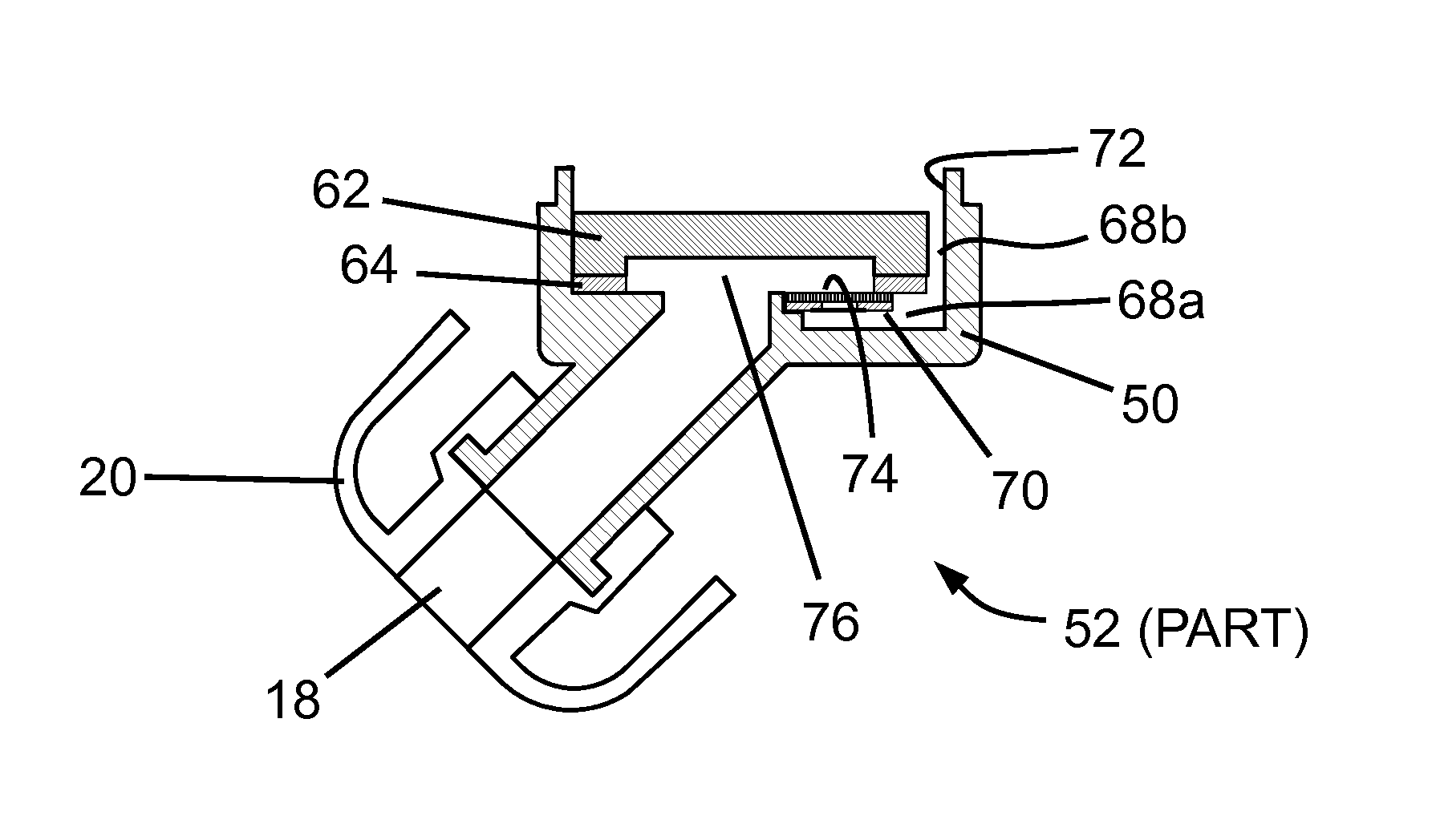
[0014]By having the microspeaker overlay, at least to a substantial extent, the recess containing the acoustic resistor, the invention facilitates the provision of acoustically resistant couple between the first (front) and second (rear) cavities without significantly increasing the lateral dimensions of the earphone housing.
[0017]In some such embodiments, the first portion of said channel is substantially linear, thereby minimising the overall length of the channel. In other preferred embodiments, the first portion of said channel is extended to follow an arcuate path beneath an edge of said microspeaker, thereby to extend the overall length of said channel.

Problems solved by technology

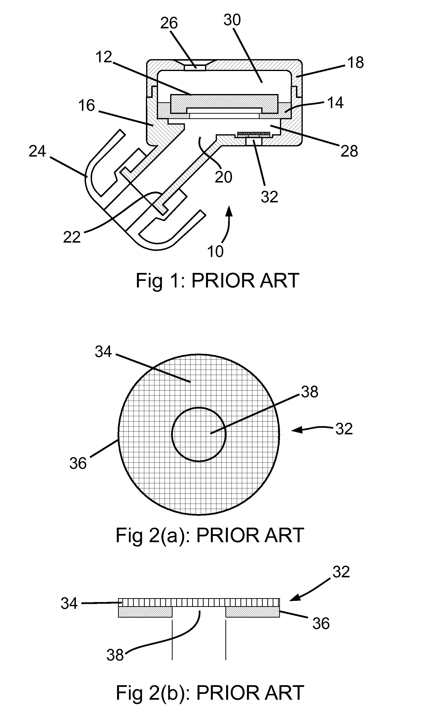
Although the thin rubber ear-bud flanges might appear to effectively “seal” the earphone assembly into the listener's ear-canal, an earphone thus positioned and located does not provide an effective acoustic seal between the listener's ear canal and the ambient environment, because low-frequency sound vibrations can still pass through the rubber flanges themselves.
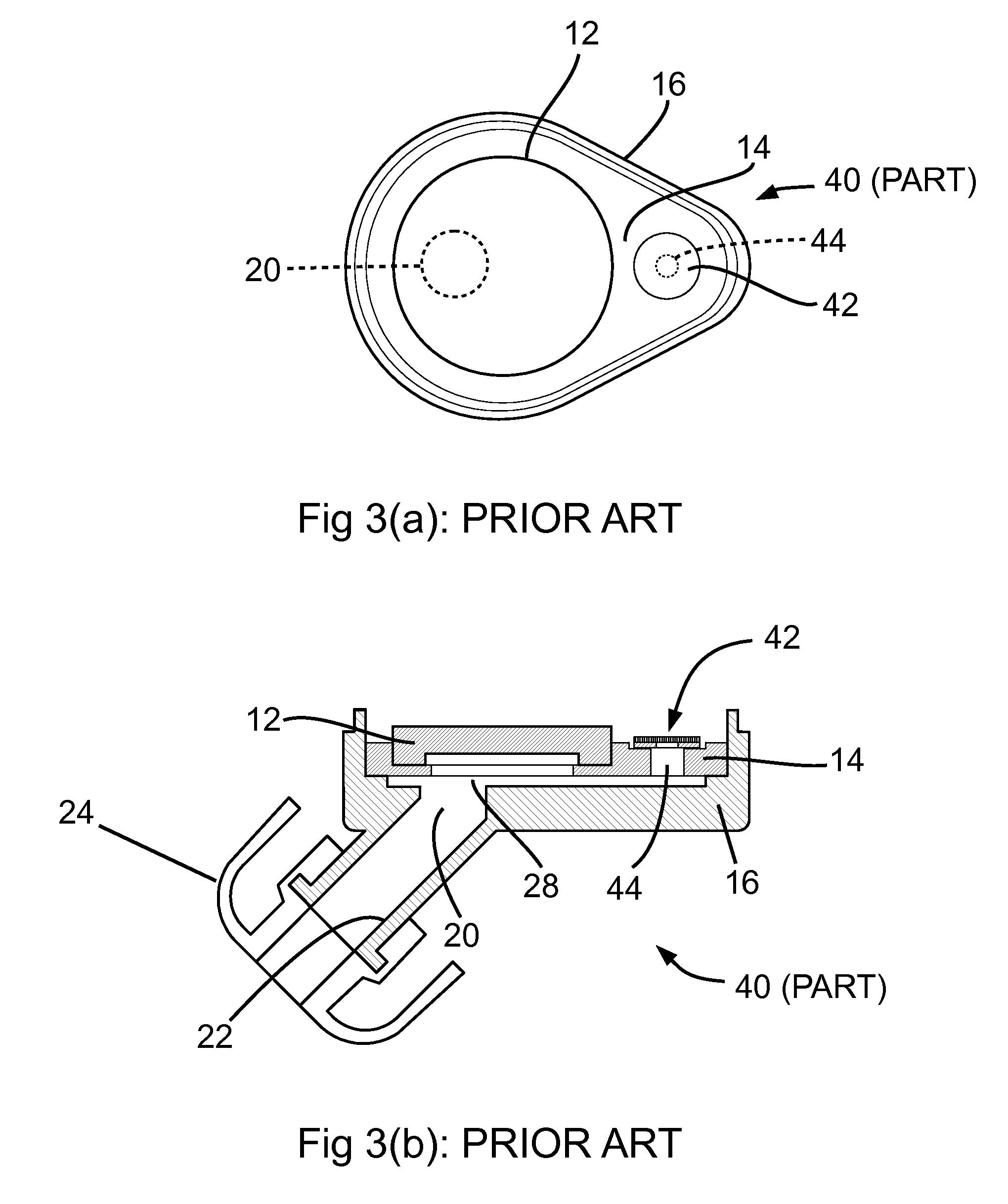
Such pathways are usually situated to provide an acoustic connection either between the outer ambient air and the internal space situated at the front surface of an internal microspeaker (or in the space behind it), or between these two internal spaces themselves, or some combination thereof, and these pathways contribute to the complexity of the acoustic structure of the earphone.

Method used


Image

  • Earphone arrangements
  • Earphone arrangements
  • Earphone arrangements

Examples


Embodiment Construction

[0033]As required, detailed embodiments are disclosed herein; however, it is to be understood that the disclosed embodiments are merely examples and that the systems and methods described below can be embodied in various forms. Therefore, specific structural and functional details disclosed herein are not to be interpreted as limiting, but merely as a basis for the claims and as a representative basis for teaching one skilled in the art to variously employ the present subject matter in virtually any appropriately detailed structure and function. Further, the terms and phrases used herein are not intended to be limiting, but rather, to provide an understandable description of the concepts.

[0034]The terms “a” or “an”, as used herein, are defined as one or more than one. The term plurality, as used herein, is defined as two or more than two. The term another, as used herein, is defined as at least a second or more. The terms “including” and “having,” as used herein, are defined as comp...


PUM


Abstract

The present invention relates to earphone arrangements configured to accommodate an acoustically-resistant couple within the compact dimensions of ear-bud type earphones, and aims to incorporate a front volume to rear volume acoustic couple into an earphone without requiring significant addition to the lateral dimensions of the earphone. The earphone has an elongate sound outlet port that locates into a listener's ear canal and bears an internal support surface which is apertured and communicates with the outlet port. A microspeaker is supported on the support surface and projects sound through the aperture and toward the outlet port. Furthermore, the housing includes a front cavity in front of the microspeaker and in communication with the outlet port, and a rear cavity behind the microspeaker. The support surface bears a recess that communicates with the front cavity, and an acoustic resistor is accommodated in the recess.

Description

CROSS REFERENCE TO RELATED APPLICATIONS[0001]This applications claims priority to United Kingdom patent application No. GB 1113075.4, filed Jul. 29, 2011, the entire contents of which are herein incorporated by reference.FIELD OF THE INVENTION[0002]The present invention relates to earphone arrangements, and it relates in particular to such arrangements as are configured to accommodate an acoustically-resistant couple within critical spatial constraints of the kind dictated by the compact dimensions of ear-bud type earphones.BACKGROUND OF THE INVENTION[0003]Acoustically-resistant couples play a significant role in determining and adjusting the acoustic characteristics and performance of earphones, especially when a particular frequency response characteristic is required. This is especially the case in the design of earphones which feature electronic ambient noise-cancellation (ANC) technology, and specifically to those utilising “ear-bud” type thin rubber flanges that seal the outle...

Claims


Application Information

Patent Timeline
Patent Type & Authority Patents(United States)
IPC IPC(8): H04R25/00H04R1/10
CPCH04R1/10H04R1/1091H04R1/2873H04R2201/105H04R1/1016H04R1/1058H04R1/1075
Inventor SIBBALD, ALASTAIRHOWLE, MARTIN
Owner INCUS LAB LTD
Why Eureka
Try Eureka