Liquid pressure motor

a technology of liquid pressure motor and piston, which is applied in the direction of fluid coupling, servomotor, coupling, etc., can solve the problems of varied braking force, loud braking noise, and serious vibration generated when the mechanism is stopped, so as to increase the working pressure, reduce the diameter of the piston, and increase the biasing spring force

Active Publication Date: 2015-03-31
NABLESCO CORP
View PDF4 Cites 3 Cited by
  • Summary
  • Abstract
  • Description
  • Claims
  • Application Information

AI Technical Summary

Benefits of technology

[0005]The present invention was done to solve the problem above, and an object of the invention is to provide a liquid pressure motor having a brake arrangement capable of restraining a pressure change of liquid discharged from a liquid pressure motor mechanism (i.e. to restrain pressure fluctuation) when the liquid pressure motor mechanism is stopped and capable of reducing the vibrations generated when the mechanism is stopped.Means for Solving Problem and Effects
[0022]According to this arrangement, since the two speed switching instruction pressure is used as a two speed switching control pressure, a pressure higher than the two-speed switching signal pressure is supplied to the back pressure chamber, and hence the pressure receiving area of the piston which is the partition is downsized (i.e. the diameter of the piston is reduced). Furthermore, since the two speed switching instruction pressure (driving pressure) is higher than the two-speed switching signal pressure, it is possible to increase the working pressure by increasing the biasing spring force.

Problems solved by technology

This induces a problem such that, for example, in a construction vehicle using the hydraulic braking device as a braking device of a driving hydraulic motor, the braking force is varied and the braking noise is loud.
Furthermore, since the on-off valve operates with a pressure higher than the setting pressure, the vibrations generated when the mechanism is stopped are serious.

Method used


Image

  • Liquid pressure motor
  • Liquid pressure motor
  • Liquid pressure motor

Examples


Embodiment Construction

[0025]The following will describe the best mode of the present invention with reference to figures. It is noted that the liquid pressure motor of the present invention is used as, for example, a driving motor of a construction vehicle such as a hydraulic excavator. While a typical medium for operating the liquid pressure motor is oil, various types of liquids may be used in place of oil. The following descriptions take as an example of the liquid pressure motor a hydraulic motor using oil as a working medium.

[0026](Structure of Hydraulic Motor)

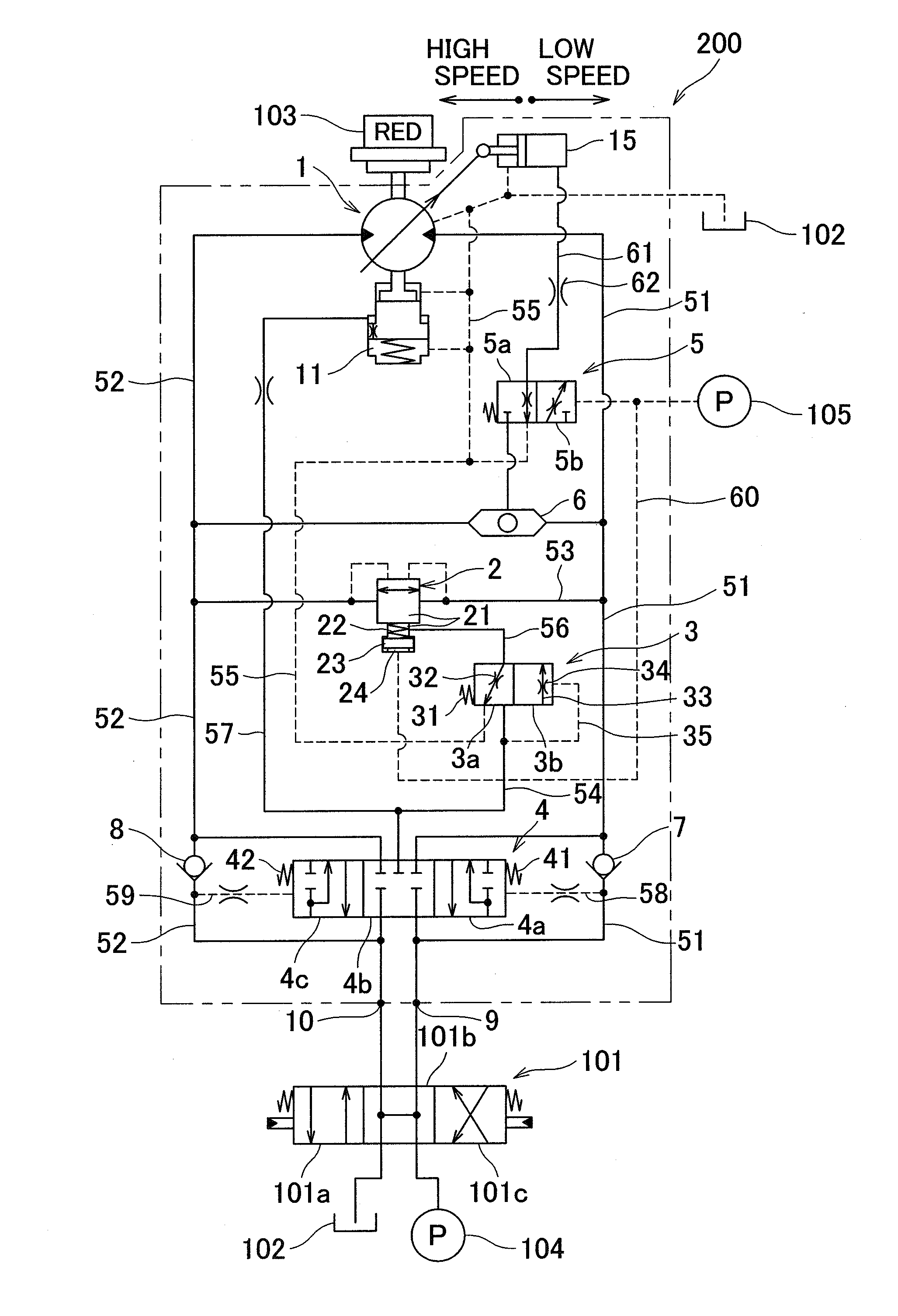
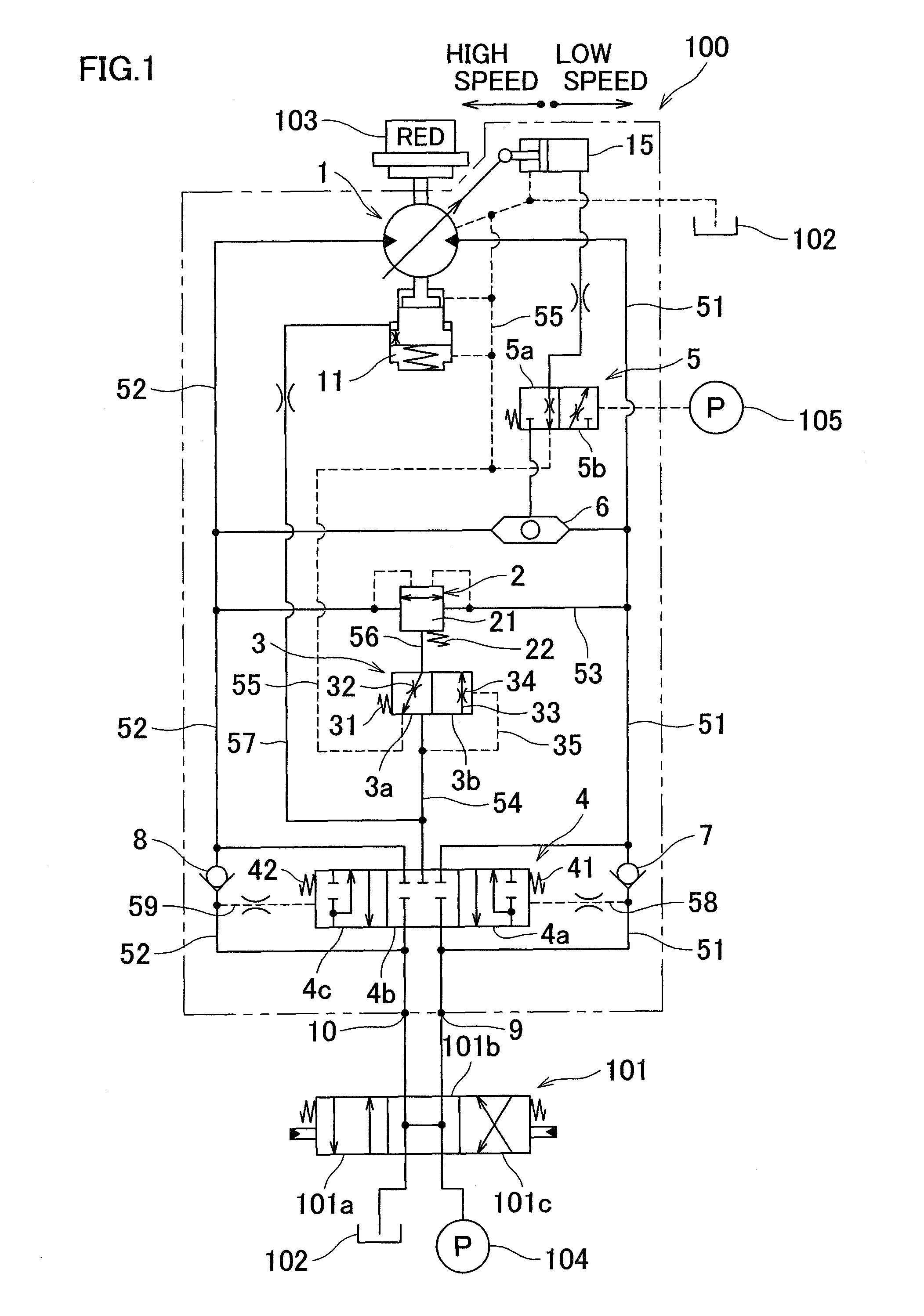
[0027]FIG. 1 is a hydraulic circuit diagram showing a hydraulic motor 100 according to an embodiment of the present invention. As shown in FIG. 1, the hydraulic motor 100 is connected to a direction switching valve 101 which controls the supply and discharge of pressure fluid, at a first inlet / outlet port 9 and a second inlet / outlet port 10. The direction switching valve 101 is connected to a pump 104 which supplies the pressure fluid to the h...


PUM


Abstract

A hydraulic motor 100 includes a switching valve 3 which is connected to a pilot passage 54 by which a pressure fluid is introduced into a back pressure chamber 21 of a relief valve 2 and takes a first changeover position 3a where the back pressure chamber 21 is connected to a tank 102 or a second changeover position 3b where the pilot passage 54 is connected to the back pressure chamber 21. By this switching valve 3, the pressure fluid supplied to a hydraulic motor mechanism 1 is introduced into the back pressure chamber 21 via the pilot passage 54 when the hydraulic motor mechanism 1 is in operation, whereas the back pressure chamber 21 is connected to the tank 102 as the pressure in the pilot passage 54 becomes not higher than a predetermined pressure when the hydraulic motor mechanism 1 is being braked.

Description

TECHNICAL FIELD[0001]The present invention relates to a liquid pressure motor which performs continuous rotary motion by using the pressure energy of liquid.BACKGROUND ART[0002]An example of technologies related to such liquid pressure motors is recited in Patent Document 1. Patent Document 1 recites a technology in regard to a braking device of a hydraulic motor. This hydraulic braking device is arranged as follows: When the hydraulic motor is driving, a pressure is introduced from a pump to a spring chamber of an on-off valve so that the on-off valve does not operate. When the hydraulic motor is stopped, a control valve returns to a neutral position so that pressure is no longer supplied to the spring chamber (back pressure chamber) of the on-off valve and hence the on-off valve becomes operable, and a braking force is generated for the hydraulic motor as the on-off valve is operated by the hydrostatic pressure from the hydraulic motor.PRIOR ART DOCUMENTSPatent Documents[0003][PAT...

Claims


Application Information

Patent Timeline
Patent Type & Authority Patents(United States)
IPC IPC(8): F15B11/04F15B11/08F16H61/4043F16H61/4157F16H63/30
CPCF15B11/08F16H61/4043F16H61/4157F15B2211/50518F15B2211/5154F15B2211/528F15B2211/6355F15B2211/67F15B2211/7058F15B2211/755F15B2211/853F15B2211/8616F16H2063/3033F15B11/00F15B13/02
Inventor SATAKE, TERUHIKOKARINO, TAKUHIRO
Owner NABLESCO CORP
Why Eureka
Try Eureka