
Recirculation infusion mash system

a mash system and mash technology, applied in the field of recirculation infusion mash system, can solve the problems of extended amount of time needed to prepare wort, difficult control of temperature in the mash tun, and poor extraction efficiency

Active Publication Date: 2015-03-31
BLICHMANN JOHN RICHARD
View PDF2 Cites 27 Cited by
  • Summary
  • Abstract
  • Description
  • Claims
  • Application Information

AI Technical Summary

Benefits of technology

The invention describes a two pot process of mashing grain into fermentable sugars. The process involves heating water in two pots, adding grain to one of the pots, circulating the water with the grain to the other pot, controlling the flow rate of the circulating water, and draining the resulting wort. The technical effects of this process include improved efficiency in the mashing process and better control over the production of fermentable sugars.

Problems solved by technology

A rate much faster than this and extraction efficiency suffers.
Their main drawback is the extended amount of time needed to prepare the wort due to the clarification and sparging process.
Additionally, brewers have a difficult time controlling temperatures in the mash tun to produce the desired wort sugar consistency.
This reduces the chances of scorching the wort which adds undesirable flavor and colors to the finished wort.
Namely, lack of wort clarification and poor efficiency.
Noting, higher ratios may not be achieved since the grains consume a significant portion of the total volume of the mash and is limited by the size of the pot.
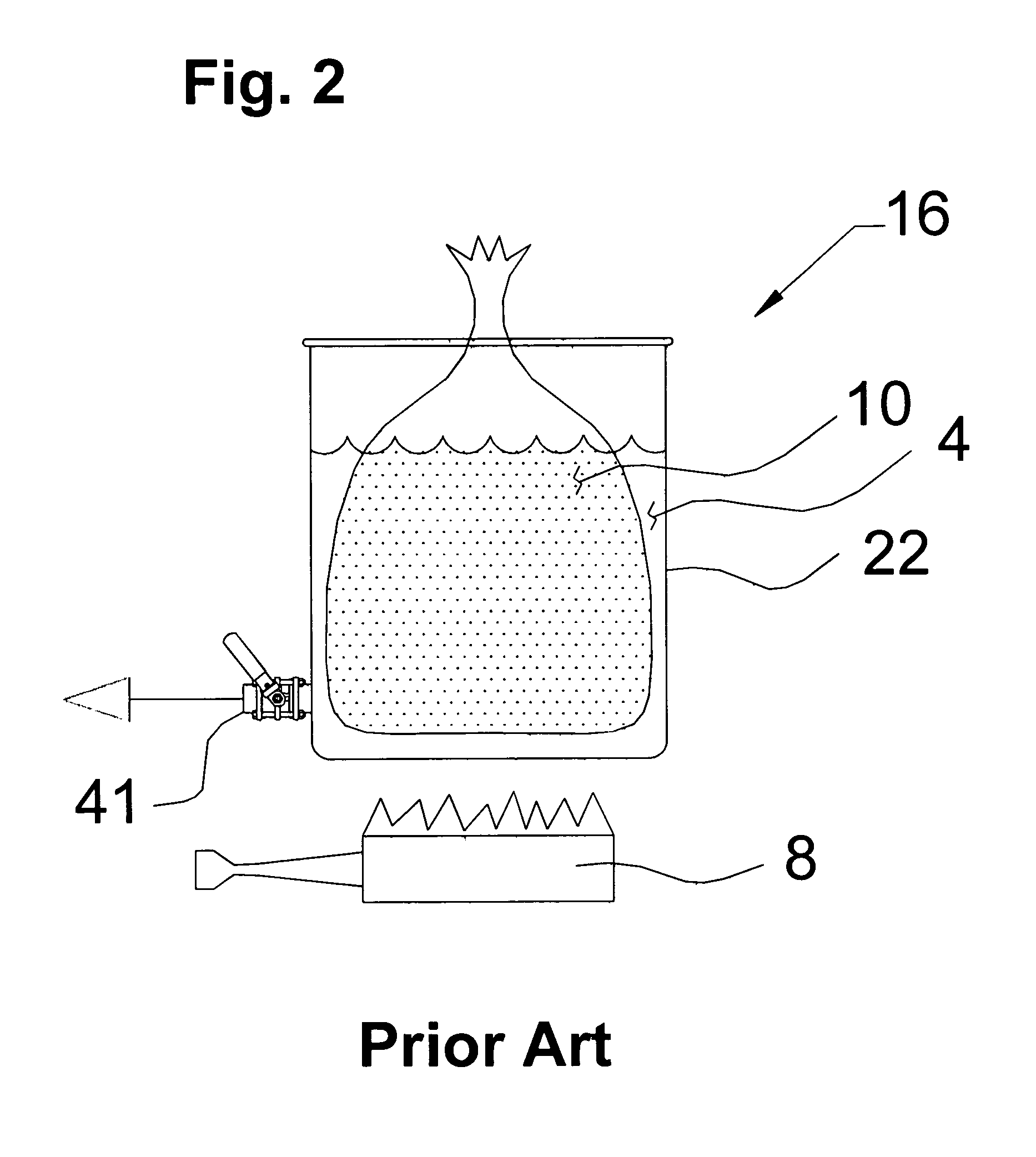
While the advantages of simplicity, low cost, and speed are clear and obvious advantages, there are equally clear disadvantages to the BIAB system.
Firstly, the elimination of recirculation precludes the clarification of the wort from the grains acting as a filter media and the resulting worts are significantly cloudier than those of 3 tier type systems and contain undesirable proteins and particulate matter which negatively impact beer quality, Secondly, it is not possible to readily perform a step mash (resting at various temperatures) since the bag impedes the heating action and leads to scorching.
Therefore cloudy wort with significantly lower efficiency (more grain is required to produce the finished beer) are produced with BIAB systems.
This a cumbersome, heavy and a somewhat dangerous operation.

Method used


Image

  • Recirculation infusion mash system
  • Recirculation infusion mash system
  • Recirculation infusion mash system

Examples


Embodiment Construction

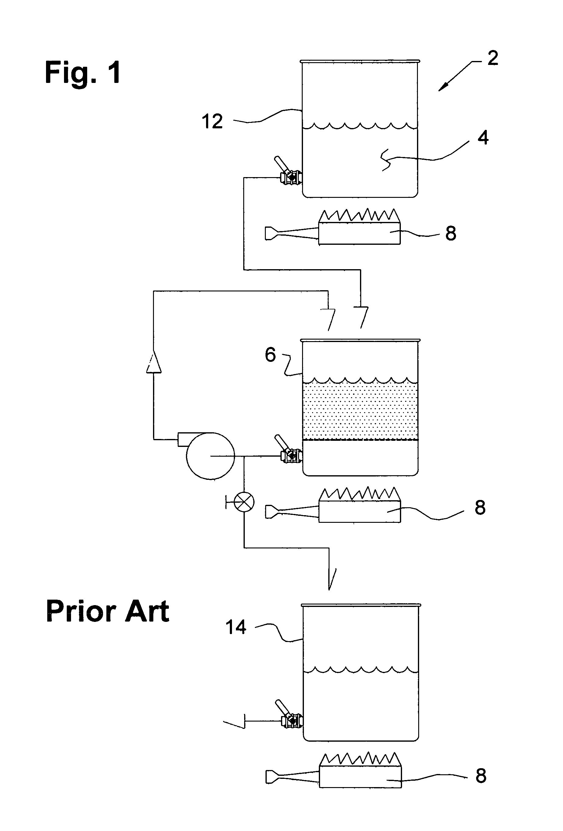
[0016]In the prior art schematic of FIG. 1, a conventional 3 tier system 2 is shown. The 3 tier setup includes a preestablished amount of water 4 placed in a first pot, a mash pot 6 and heated by a heating unit 8 to a preestablished temperature. Grain 10 is added at the preestablished temperature and the preestablished temperature is stabilize. Separately, a preestablished amount of sparge (rinse) water 4 is added to a second pot, hot liquor tank (HLT) 12. The hot liquor tank 12 is heated to a preestablished temperature and held at that temperature until needed for sparging at the end of a mashing process 24 within a third pot 14. Thus, the 3 tier system uses three (3) pots 6, 12, 14.

[0017]In the prior art 3 tier system of FIG. 1, a predetermined volume of water 4 is placed in the hot liquor tank 12 and a remainder of the water 4 is placed in the mash pot 6. In general, about half of the total water 4 needed for the brew is added to each pot 12, 6. It is recognized that this ratio c...


PUM

PropertyMeasurementUnit
specific gravityaaaaaaaaaa
physical contacting relationshipaaaaaaaaaa
liquid transfer mechanismaaaaaaaaaa

Abstract

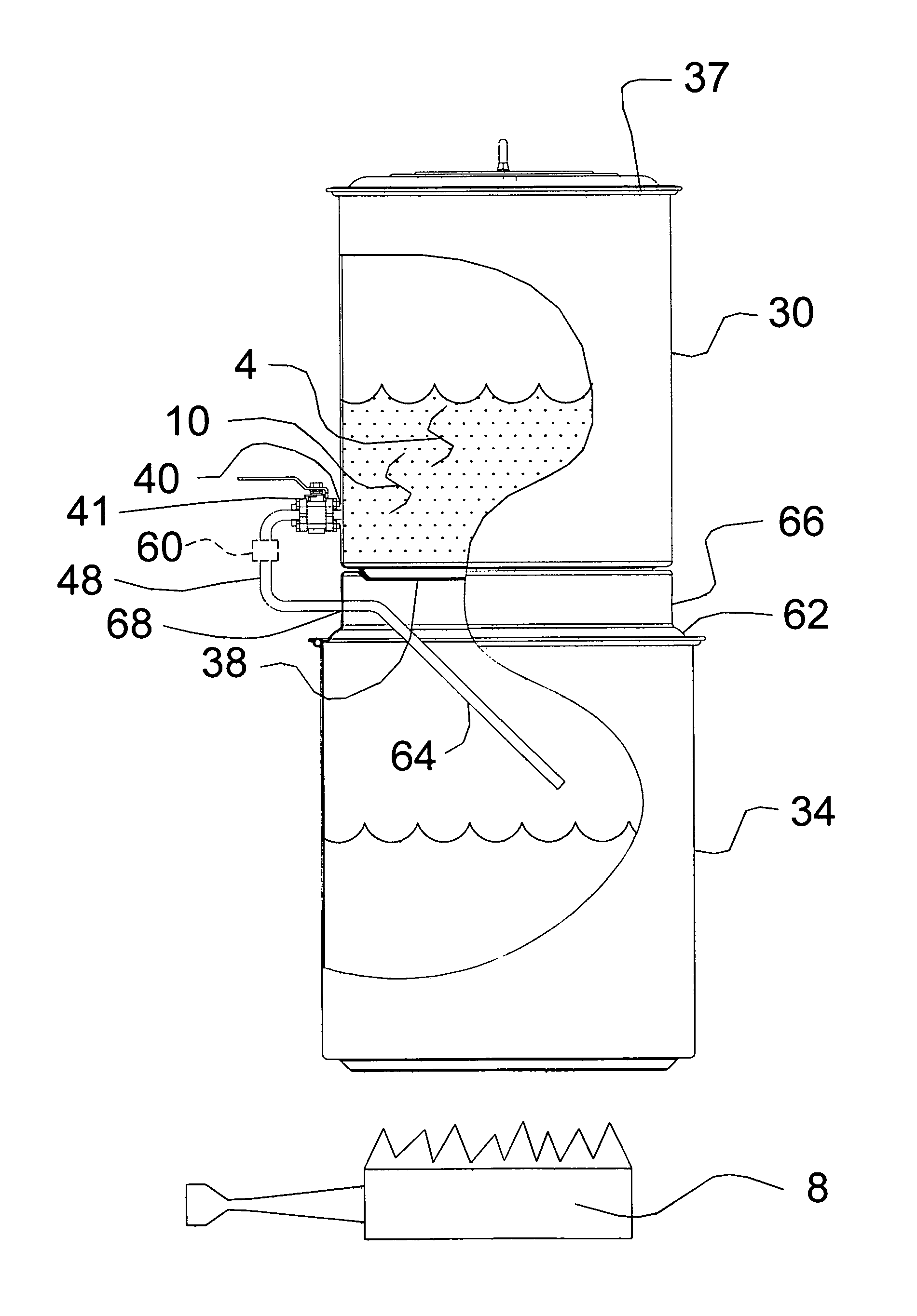
A process of mashing grain into fermentable sugar wherein two pots are used in the process. A first pot and a second pot is partially filled with water. Heat is added to the first pot. Heat is transferred to the second pot by transferring the water from the first pot to the second pot at a preestablished rate. Grain is added to the second pot which in conjunction with the water forms a wort. The wort is drained from the second pot to the first pot.

Description

TECHNICAL FIELD[0001]This invention relates generally to a system or a process for mashing grain into a fermentable sugar.BACKGROUND[0002]It is well known in the art to use a 3 tier system to produce beer wort from crushed grains. A typical system utilizes a first vessel for boiling the finished wort. A second vessel called a mash and lauter tun for mashing the grains which will contain a false bottom or a slotted pipe manifold or a simple screen on the drain fitting. A third vessel called a hot liquor tank (HLT) is simply a tank for heating the rinse water for the spent grains. Although uncommon, sometimes a combined mash lauter tun is not used and the wort is transferred from the mash tun to the lauter tun for wort (unfermented beer) separation. To prepare the wort, the mash tun is filled with a preestablished quantity of water and heated to a preestablished temperature. Typically, a water to grist ratio of 1 to 2 quarts of water per pound of grain is used. The crushed grains are ...

Claims


Application Information

Patent Timeline
Patent Type & Authority Patents(United States)
IPC IPC(8): C12C1/00C12C7/04
CPCC12C7/042C12C7/06C12C13/10
Inventor BLICHMANN, JOHN RICHARD
Owner BLICHMANN JOHN RICHARD
Learn More