Supercharge Your Innovation With Domain-Expert AI Agents!

Tension link for drill floor substructure assembly

a technology of tension link and drill floor, which is applied in the direction of flooring, building repairs, parkings, etc., can solve the problems of limiting the size and capacity of rigs that can be transported and used, time and cost of moving, and preventing the separation of drill floor and the first and second link elements

Inactive Publication Date: 2015-04-07
T & T ENG SERVICES
View PDF6 Cites 2 Cited by
  • Summary
  • Abstract
  • Description
  • Claims
  • Application Information

AI Technical Summary

Benefits of technology

Effectively resists separation forces at the drill floor level, maintaining structural integrity and stability during transportation and operation without increasing costs or complexity, while maintaining compatibility with existing rig designs and procedures.

Problems solved by technology

This requirement results in extensive disassembly of full-size drilling rigs to maintain a maximum transportable width and transportable height with further restrictions on maximum weight, number and spacing of axles, and overall load length and turning radius.
These transportation constraints vary from state to state, as well as with terrain limitations.
These constraints can limit the size and capacity of rigs that can be transported and used, conflicting with the subterranean requirements to drill deeper, or longer, and reach horizontal wells more quickly, requiring larger rigs.
Larger rigs require a wider base structure for strength and wind stability, and this requirement conflicts with the transportability constraint and the time and cost of moving them.

Method used


Image

  • Tension link for drill floor substructure assembly
  • Tension link for drill floor substructure assembly
  • Tension link for drill floor substructure assembly

Examples


Embodiment Construction

[0022]The following description is presented to enable any person skilled in the art to make and use the invention, and is provided in the context of a particular application and its requirements. Various modifications to the disclosed embodiments will be readily apparent to those skilled in the art, and the general principles defined herein may be applied to other embodiments and applications without departing from the spirit and scope of the present invention. Thus, the present invention is not intended to be limited to the embodiments shown, but is to be accorded the widest scope consistent with the principles and features disclosed herein.

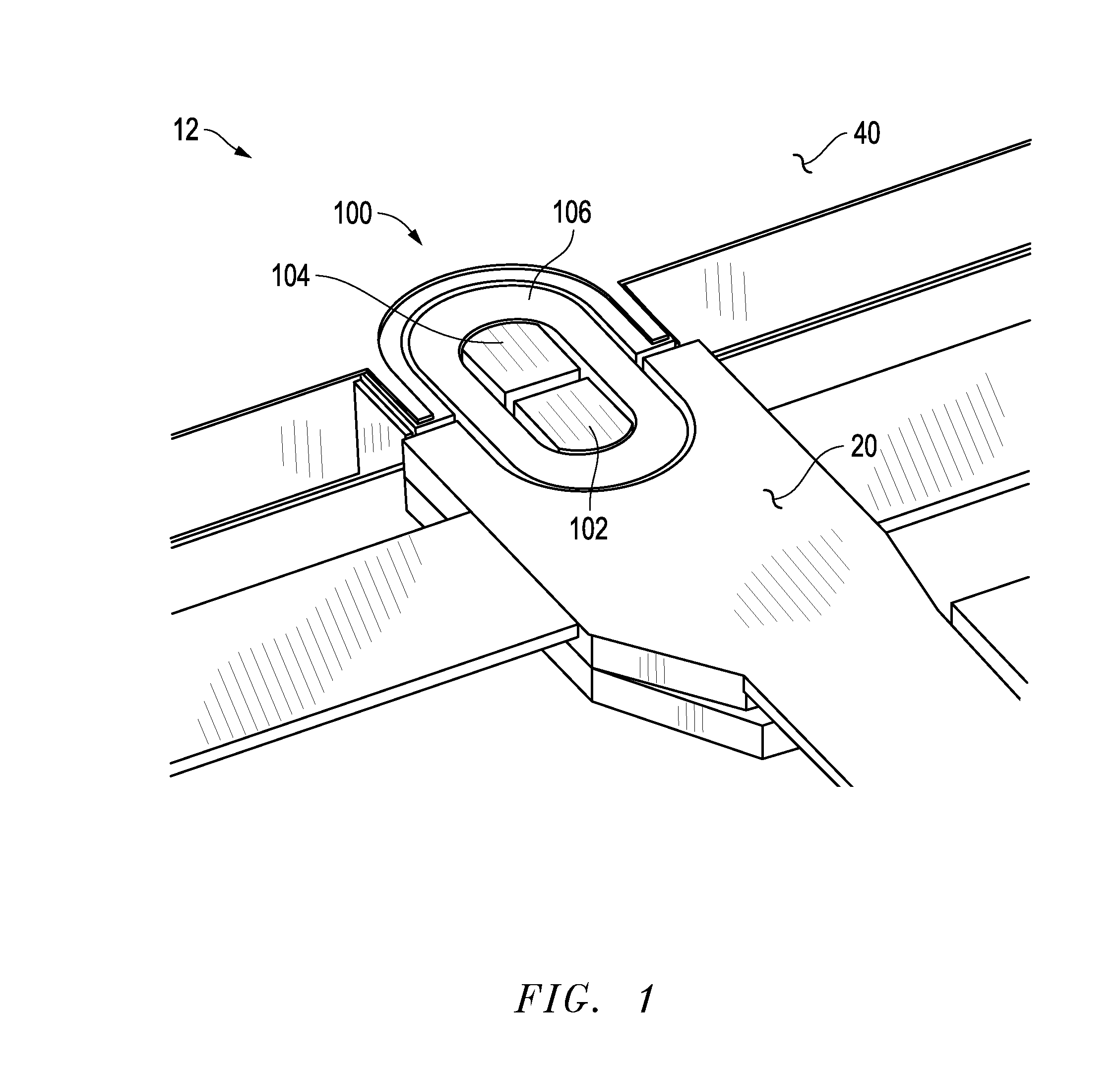
[0023]FIG. 1 is an isometric view of a drill floor level locking system having certain features in accordance with the present invention.

[0024]In this embodiment, a drilling rig 10 is provided (not shown), comprising a collapsible substructure 12 including a side top box 20, and a center section 40 connectable to side top box 20. A drill floor ...


PUM


Abstract

The present invention relates to a new tension link drill floor level connection system for use on a drilling rig, as may be used in subterranean exploration. The present invention provides a tension link assembly for resisting separating forces incurred between sections of the substructure. In particular, the tension link assembly may be located at the drill floor level for resisting the separating forces imparted by “splayed” or wide leg mast structures that tend to separate substructure side boxes from the substructure center section. The present invention may be comprised of a first link element and a second link element with a tension link being connectable over the first and second link elements to resist separation between sections of the substructure. A latch mechanism may be utilized to prevent upward movement of the tension side boxes or center section relative to the drill floor or to one another.

Description

TECHNICAL FIELD OF INVENTION[0001]The present invention relates to a new tension link drill floor level connection system for use on a drilling rig, as may be used in subterranean exploration. The present invention provides a tension link for resisting separating forces incurred between sections of the substructure. In particular, the invention provides a mechanism at the drill floor level that resists the separating forces imparted by “splayed” or wide leg mast structures that tend to separate substructure side boxes from the substructure center section. In an alternative embodiment of the invention, a latch mechanism is also provided to prevent vertical movement of sections of the substructure.BACKGROUND OF THE INVENTION[0002]In the exploration of oil, gas and geothermal energy, drilling operations are used to create boreholes, or wells, in the earth. Drilling rigs used in subterranean exploration must be transported to the locations where drilling activity is to be commenced. The...

Claims


Application Information

Patent Timeline
Patent Type & Authority Patents(United States)
IPC IPC(8): E04B5/02E21B15/00
CPCE21B15/00E04B1/388
Inventor SOUCHEK, RICHARD D.ORGERON, KEITH J.
Owner T & T ENG SERVICES
Features
  • R&D
  • Intellectual Property
  • Life Sciences
  • Materials
  • Tech Scout
  • Unparalleled Data Quality
  • Higher Quality Content
  • 60% Fewer Hallucinations
Learn More