Slotted turbine airfoil

a turbine and airfoil technology, applied in the direction of machines/engines, stators, liquid fuel engines, etc., can solve the problems of high speed and local wetness concentration of steam passing through these stages, erode the tip regions of rotating buckets, and the walls of static nozzle airfoils, and both conventional approaches have respective downsides. the cost of such protection can be significan

Active Publication Date: 2015-04-07
GENERAL ELECTRIC CO
View PDF14 Cites 4 Cited by
  • Summary
  • Abstract
  • Description
  • Claims
  • Application Information

AI Technical Summary

Problems solved by technology

In some stages of a turbine (e.g., the last stages of a low-pressure steam turbine section), the high speed and local wetness concentration of steam passing through these stages can erode the tip regions of rotating buckets, as well as the walls of the static nozzle airfoils.
However, both of these conventional approaches have respective downsides.
In the case of hardening or shielding, the costs associated with such protection can be significant.
In the case of conventional hollow airfoils with pressure or suction slots, theses airfoils and slots can be difficult to manufacture, and can be difficult to weld into the turbine diaphragm rings without causing distortion in the airfoil.

Method used


Image

  • Slotted turbine airfoil
  • Slotted turbine airfoil
  • Slotted turbine airfoil

Examples


Embodiment Construction

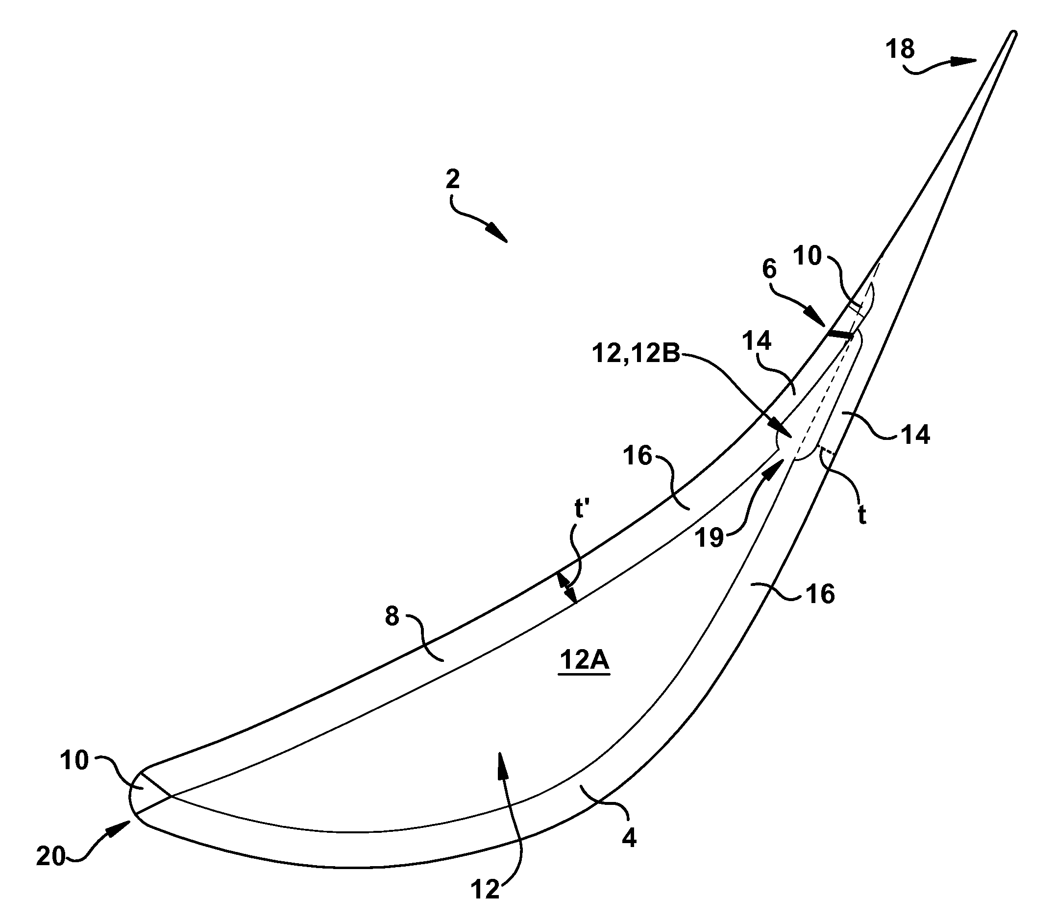
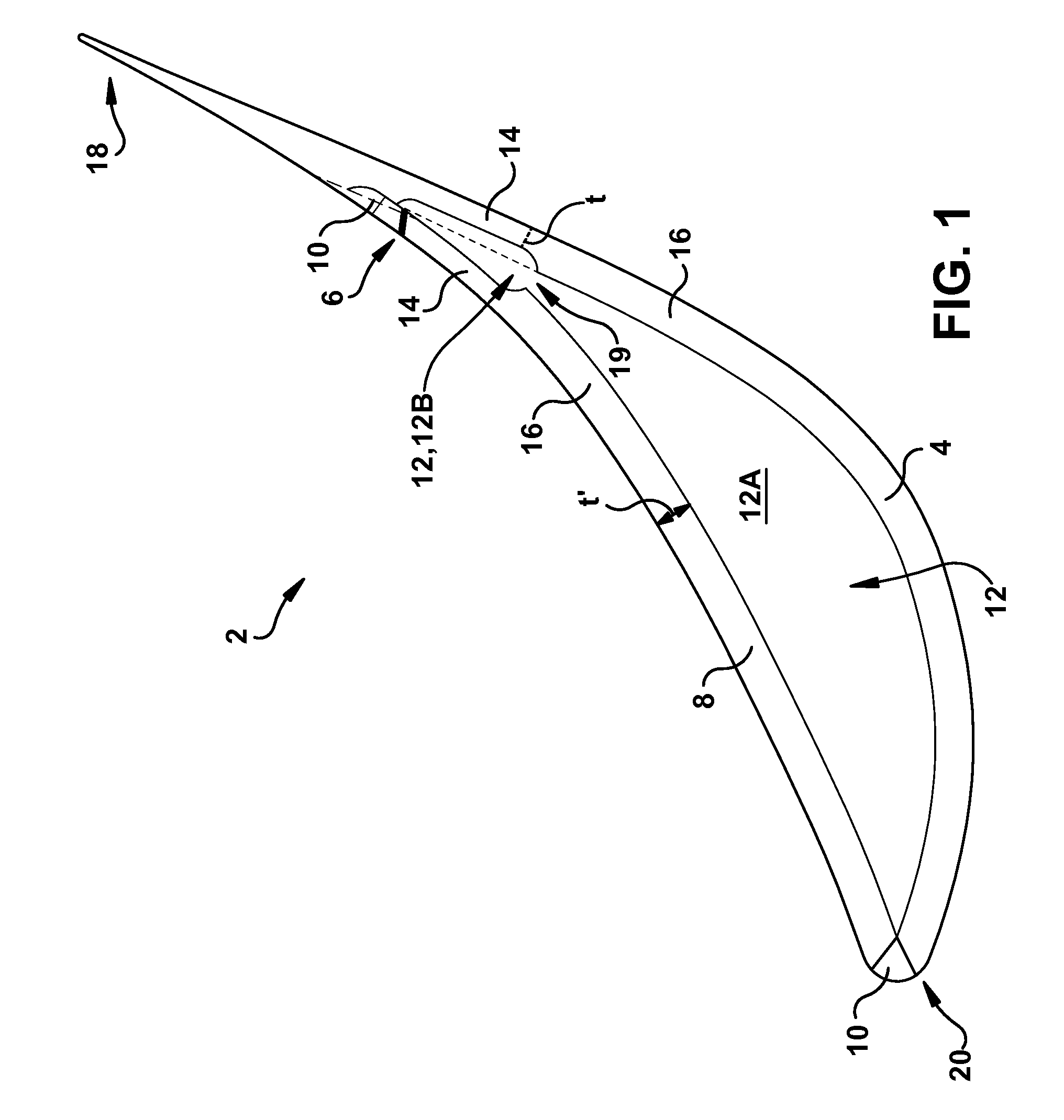
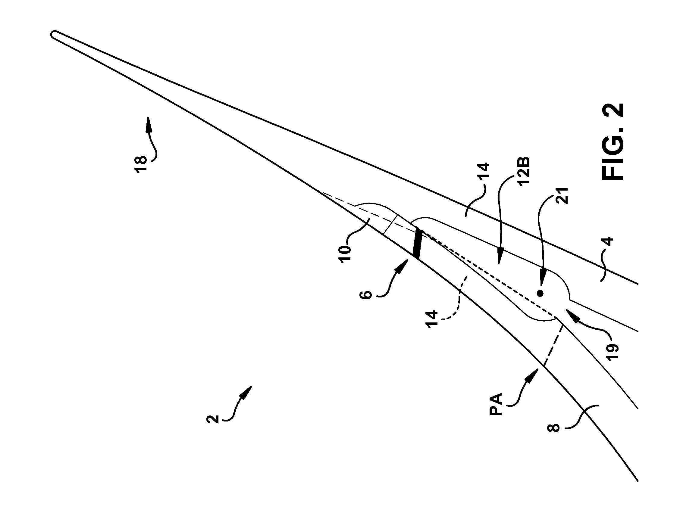
[0012]The subject matter disclosed herein relates to a slotted turbine airfoil. More particularly, aspects of the invention include a turbine airfoil having a moisture diverting slot for increasing the efficiency of a turbine stage including that airfoil.

[0013]In some stages of a turbine (e.g., the last stages of a low-pressure steam turbine section), the high speed and local wetness concentration of steam passing through these stages can erode the tip regions of rotating buckets, as well as the walls of the static nozzle airfoils. In order to combat the erosive effects of the steam in this region, manufacturers conventionally harden the bucket airfoil leading edges near the tip region, or shield the area with satellite strips. Another conventional approach involves removing accumulated water through water drainage arrangements in the nozzle outer sidewalls (or, endwalls), or through pressure and / or suction slots made in hollow static nozzle airfoils. This moisture is then collected...


PUM


Abstract

A slotted turbine static nozzle airfoil. In one embodiment, the turbine static nozzle airfoil includes a concave pressure wall having a slot extending therethrough; a convex suction wall adjoined with the concave pressure wall at respective end joints; and a pocket fluidly connected with the slot and located between the convex suction wall and the concave pressure wall, wherein at least one of the convex suction wall or the concave pressure wall includes a thinned segment proximate one of the respective end joints, the thinned segment configured to extend the pocket toward a trailing edge of the turbine static nozzle airfoil.

Description

BACKGROUND OF THE INVENTION[0001]The subject matter disclosed herein relates to a slotted turbine airfoil. More particularly, aspects of the invention include a turbine airfoil having a moisture diverting slot for increasing the efficiency of a turbine stage including that airfoil.[0002]In some stages of a turbine (e.g., the last stages of a low-pressure steam turbine section), the high speed and local wetness concentration of steam passing through these stages can erode the tip regions of rotating buckets, as well as the walls of the static nozzle airfoils. In order to combat the erosive effects of the steam in this region, manufacturers conventionally harden the bucket airfoil leading edges near the tip region, or shield the area with satellite strips. Another conventional approach involves removing accumulated water through water drainage arrangements in the nozzle outer sidewalls (or, endwalls), or through pressure and / or suction slots made in hollow static nozzle airfoils. This...

Claims


Application Information

Patent Timeline
Patent Type & Authority Patents(United States)
IPC IPC(8): F01D9/02F01D9/04F01D5/18
CPCF01D5/187F05B2230/232F05B2260/95F01D5/147F01D25/32F05D2220/31F05D2260/602
Inventor BURDGICK, STEVEN SEBASTIANDI SANTE, ALBERTO
Owner GENERAL ELECTRIC CO
Why Eureka
Try Eureka