Noninvasive method to measure intracranial and effective cerebral outflow pressure

a technology of intracranial pressure and measurement method, which is applied in the field of non-invasive measurement and monitoring of the absolute value of intracranial pressure, can solve the problems of varying degrees of invasiveness, brain damage and infection, and the automatic regulation system is often non-functional, so as to minimize brain exposure to high-intensity acoustic energy and facilitate the effect of performing

Active Publication Date: 2015-04-07
PRANEVICIUS HENRIKAS +3
View PDF1 Cites 11 Cited by
  • Summary
  • Abstract
  • Description
  • Claims
  • Application Information

AI Technical Summary

Benefits of technology

[0019]The inventive method is based in sound biophysical principles, is easily performed by personnel without special training, requires little or no calibration, allow measurements outside the ICU, for example, ambulatory, field and home settings, provides reproducible measurements for the monitoring purposes, operates independently of the presence of external head and / or orbital injuries, and minimizes brain exposure to high intensity acoustic energy. For that matter, the inventive system for measuring intracranial pressure noninvasively and determining whether CPP depends on ICP or CVP is relatively inexpensive.
[0024]In another embodiment, the system comprises one or more near infrared spectroscopy (NIRS) sensors positioned at the subject cranium for identifying changes in outgoing blood flow as a function of detected pulsed excitations. Pulsed excitations follow either the cardiac cycle or the breathing cycle. The pulsed excitations are generated by a cuff and cuff controller of by an oscillatory device positioned proximate a jugular vein. Controlled occlusion is achieved by creating hydrostatic gradient between the point of cranial blood outflow and the right atrium of the subject's heart though tilting to decrease a difference between the internal intravascular pressure and external atmospheric pressures.

Problems solved by technology

These automatic regulation systems are often non-functional in brain trauma, stroke, hydrocephalic patients, and patients with liver or kidney failure, so that monitoring and management of ICP becomes a critical aspect of medical care.
These have varying degrees of invasiveness.
The invasive methods, although medically accepted and routinely used, suffer from several drawbacks: (I) the transducer has to be calibrated before insertion; (2) the placement of the system requires a highly-trained individual; (3) there is a relatively short term (2-3 days) reliability and stability of the system, either because of leaks or plugging of the transducer, or inadvertently being disturbed, or being pulled out; (4) there are also associated risks of transducer placement such as brain damage and infection.
There are also additional drawbacks to current measurement techniques, for example:a) many non-invasive techniques are not based on sound biophysical principles or do not take into account the interrelationship between biophysical principles;b) many current techniques require expensive equipment and do not utilize existing equipment on hand;c) many current techniques cannot be easily performed by personnel without special training;d) most apparatus utilized for invasive techniques require accurate and of course regular calibration;e) for the most part, invasive techniques allow measurements only in the limited setting of an intensive care unit, e.g., not in ambulatory, in field, in non-acute care community nor private in-home settings;f) some current techniques do not always provide for reproducible measurements for the monitoring purposes;g) known non-invasive techniques require head or orbital contact, ruling out use in patients with external head and / or orbital injuries -the specific patient population who likely need this measurement most; andh) many known non-invasive techniques use ultrasound and as such expose brain to the high intensity acoustic energy.

Method used


Image

  • Noninvasive method to measure intracranial and effective cerebral outflow pressure
  • Noninvasive method to measure intracranial and effective cerebral outflow pressure
  • Noninvasive method to measure intracranial and effective cerebral outflow pressure

Examples


Embodiment Construction

[0048]The following is a detailed description of example embodiments of the invention depicted in the accompanying drawings. The example embodiments are in such detail as to clearly communicate the invention and are designed to make such embodiments obvious to a person of ordinary skill in the art. However, the amount of detail offered is not intended to limit the anticipated variations of embodiments; on the contrary, the intention is to cover all modifications, equivalents, and alternatives falling within the spirit and scope of the present invention, as defined by the appended claims.

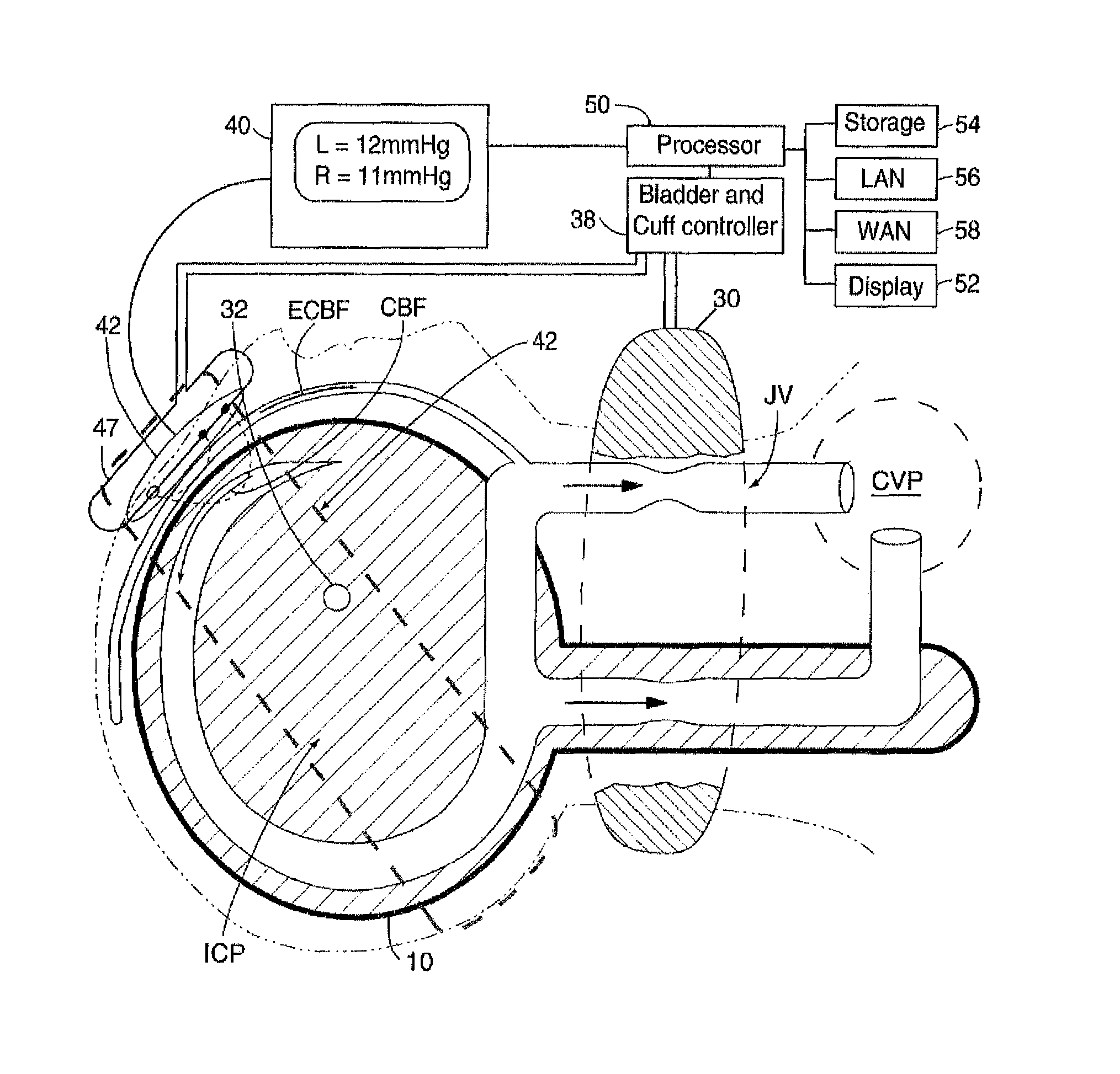
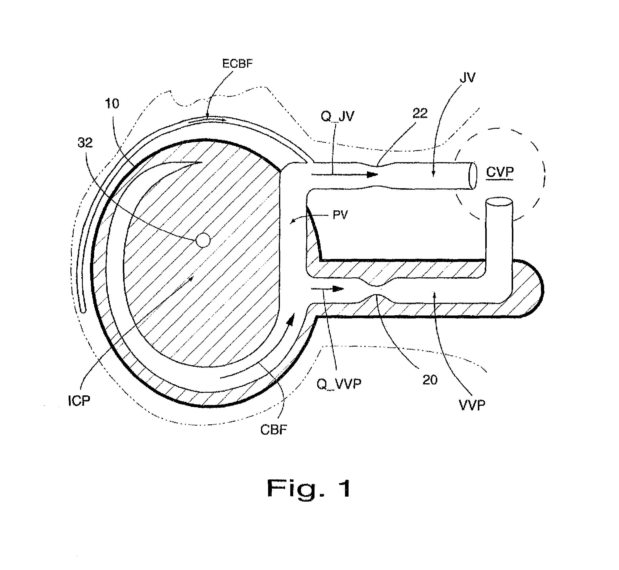
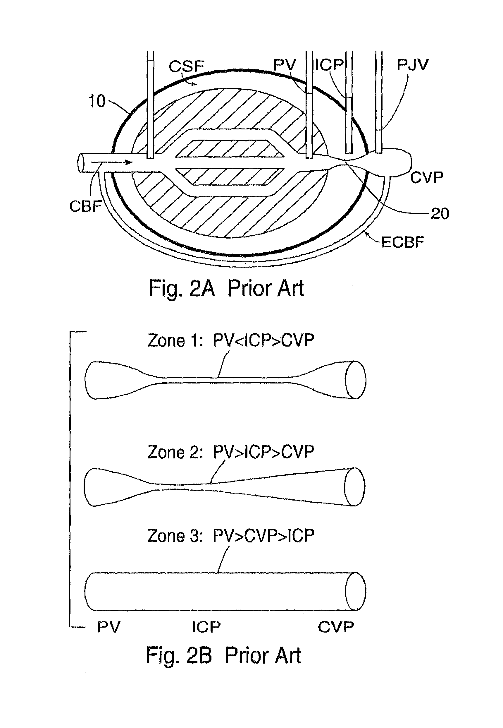
[0049]The invention provides method and apparatus for detecting and measuring increased global or local intracranial pressure (ICP) (both invasively and non-invasively) as well as whether ICP or CVP determines effective cerebral outflow pressure. The theoretical basis of the invention has a theoretical basis in an intracranial model based on the Starling resistor; Luce, J M, Huseby, J S, Kirk W, Butl...


PUM


Abstract

A system for detecting and measuring increased global or local intracranial pressure includes various devices for performing controlled occlusion of jugular cranial blood outflow and generating occlusion data related to said controlled occlusion, a cranial blood outflow pressure measurement device and a processor for processing jugular cranial blood outflow occlusion data and cranial blood outflow data to identify and / or measure a functional relationship between the jugular controlled occlusion and the jugular cranial blood outflow pressure. A device communicates the functional relationship a display device and / or a patient monitoring system. The processor also detects a state of equilibrium between the jugular cranial blood outflow pressure and the jugular occlusion pressure at occlusion. In yet another embodiment, intracranial and extracranial vessel compliance is measured by NIRS system, the equilibrated using external compression bladder, and equilibrium bladder pressure is displayed as local intracranial pressure.

Description

CROSS-REFERENCE TO RELATED APPLICATIONS[0001]This application is a continuation-in-part of patent application Ser. No. 11 / 954,227, filed on Dec. 12, 2007, and claims priority thereto in part under 35 U.S.C.§120 therefrom, all of the contents of which are incorporated by reference herein.BACKGROUND OF THE INVENTION[0002]The present invention relates broadly to the non-invasive measurement and monitoring of the absolute value of intracranial pressure.[0003]Intracranial pressure (ICP) is closely related to cerebral blood flow (CBF). To a first approximation, CBF is determined by the cerebral perfusion pressure (CPP), due to their respective proportionality (CBF=CPP / Resistance). CPP is the difference between arterial blood pressure (BP) and intracranial pressure (ICP), that is, CPP=BP−ICP. Increase in ICP results in smaller values of CPP and CBF. Because of the difficulty of measuring CBF directly, BP and ICP are often measured to assess CPP. In a healthy individual, automatic regulatio...

Claims


Application Information

Patent Timeline
Patent Type & Authority Patents(United States)
IPC IPC(8): A61B5/05A61B5/00A61B5/021A61B5/0215A61B5/03A61B5/113A61B8/04A61B8/08
CPCA61B5/031A61B5/02108A61B5/0215A61B5/02152A61B5/113A61B8/04A61B8/488A61B2562/0219A61B8/0808G16H40/63
Inventor PRANEVICIUS, HENRIKASPRANEVICIUS, MINDAUGASPRANEVICIUS, OSVALDASLIEBESKIND, DAVID
Owner PRANEVICIUS HENRIKAS
Why Eureka
Try Eureka