Al technical title is built by PatSnap Al team. It summarizes the technical point description of the patent document.
a virtual badge and badge technology, applied in the field of virtual badges, can solve problems such as rendering virtual badges useless immediately
Inactive Publication Date: 2015-04-07
SPHINX IND INC
View PDF105 Cites 14 Cited by
Summary
Abstract
Description
Claims
Application Information
AI Technical Summary
This helps you quickly interpret patents by identifying the three key elements:
Problems solved by technology
Method used
Benefits of technology
[0011]A virtual badge, which can be tracked if desired, can contain customizable data, photos, and / or images, which are scannable for various applications. The virtual badge is displayed on an electronic device, such as a smart cell phone, and replicates what a typical plastic badge can display. The virtual badge system can also incorporate the capability to send a wireless electronic message to a local printer. The printer prints out a replication of the virtual badge, including its scannable images or other identifiable information, to a non-electronic medium, such as paper or a temporary, sticker badge, which then can be attached to a user's clothing. Random check points could scan this paper rendition of the virtual badge, providing possible tracking enhancement of visitors to a facility.
[0085]It is yet a further objective of the invention to provide a system and a method to ensure data integrity and transmission success for virtual badges via a sync through a Wi-Fi network or Mesh Wi-Fi network with BLUETOOTH® or other wireless technology in an extremely limited or no connectivity environment so as to aid in transmission and / or preserve the battery life of the electronic device while it is using a virtual badge.
Problems solved by technology
Similarly, an administrator could choose to send a non-scheduled, self-destruct message to the device and immediately render the virtual badge useless.
Method used
Image
Click on the blue label to locate the original text in one second.
Reading with bidirectional positioning of images and text.
Examples
Embodiment Construction
[0122]While the present invention is a susceptible embodiment in various forms, there is shown in the drawings and will hereinafter be described a presently preferred, albeit not limiting, embodiment with the understanding that the present disclosure is to be considered an exemplification of the present invention and is not intended to limit the invention to the specific embodiments illustrated.
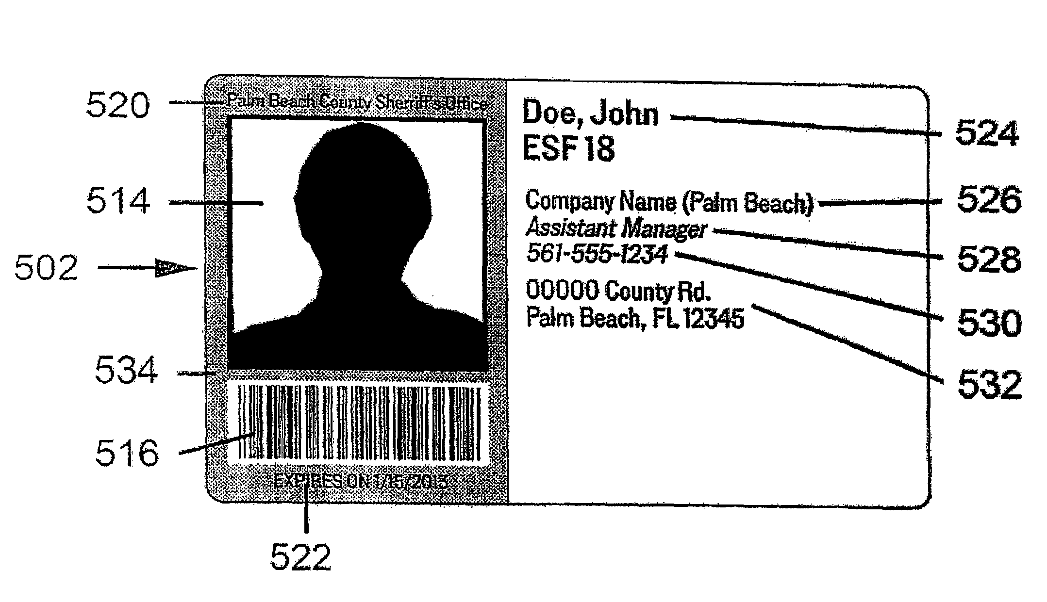
[0123]The present invention creates a system comprising of “backend” software (software adapted to provide necessary functionality for server) on a web based, cloud based, or laptop server synchronized with a “front-end” software, such as software adapted to be used by a display device, including an electronic display device capable of displaying images or text, such as a cell phone or tablet computer, to make the device function accordingly, i.e. properly display the information as a virtual badge, displayed on the electronic display device. The backend software system is designed for, but i...
PUM
Abstract
A system, methods, and devices comprising a virtual badge are disclosed. The virtual badge can be displayed on an electronic device or on another linked or unlinked portable device. For use in both emergency and non-emergency scenarios, the virtual badge comprises images and data which can be scanned, and the capability to alternate colors and / or self-destruct on a pre-set schedule. The system, methods, and devices may use a self-destruct mechanism which renders the virtual badge unusable. Using plugin technologies, the system optionally can enable field collected photos and notes on customizable forms to be mapped, tracked, and time / date stamped, including in a 100% disconnected environment. A modifiable virtual badge can aid in credentialing via certifications and qualifications, inventory, accountability, organization, and efficiency. The system, methods, and devices are designed to aid in access control, and other activities, such as data collection, inventory, accountability, payment gateways, and site management.
Description
REFERENCE TO RELATED APPLICATIONS[0001]In accordance with 37 C.F.R 1.76, a claim of priority is included in an Application Data Sheet filed concurrently herewith. Accordingly, the present is a continuation-in-part to U.S. patent application Ser. No. 13 / 661,555, filed on Oct. 26, 2012, entitled, “VIRTUAL BADGE, DEVICE AND METHOD” which claims priority to U.S. Provisional Patent Application No. 61 / 709,844, filed on Oct. 4, 2012; entitled, “VIRTUAL BADGE, DEVICE AND METHOD”, and is a continuation-in-part of U.S. patent application Ser. No. 13 / 536,618, filed Jun. 28, 2012, entitled, “GPS PATHFINDER CELL PHONE AND METHOD”, which is a continuation-in-part of U.S. patent application Ser. No. 13 / 524,724, filed Jun. 15, 2012, entitled, “GPS PATHFINDER CELL PHONE AND METHOD”, which is a continuation-in-part of application U.S. patent application Ser. No. 13 / 296,874, filed Nov. 15, 2011, entitled, “GPS PATHFINDER CELL PHONE AND METHOD”, which is a continuation-in-part of application U.S. paten...
Claims
Application Information
Patent Timeline
Application Date:The date an application was filed.
Publication Date:The date a patent or application was officially published.
First Publication Date:The earliest publication date of a patent with the same application number.
Issue Date:Publication date of the patent grant document.
PCT Entry Date:The Entry date of PCT National Phase.
Estimated Expiry Date:The statutory expiry date of a patent right according to the Patent Law, and it is the longest term of protection that the patent right can achieve without the termination of the patent right due to other reasons(Term extension factor has been taken into account ).
Invalid Date:Actual expiry date is based on effective date or publication date of legal transaction data of invalid patent.