Timepiece wheel set with peripheral guiding

a technology of timepiece wheels and wheel sets, applied in the field of timepiece wheel sets, can solve the problems of limited performance of timepiece movements, and inability to use wheel sets made of fragile materials such as silicon or similar, and achieve the effect of low shock sensitivity and low inertia

Inactive Publication Date: 2015-04-14
BLANCPAIN SA
View PDF9 Cites 0 Cited by
  • Summary
  • Abstract
  • Description
  • Claims
  • Application Information

AI Technical Summary

Benefits of technology

[0013]The invention proposes to overcome the drawbacks of the prior art by proposing a method of guiding wheel sets, in particular timepiece wheel sets with lower inertia and / or higher angular velocity, which guarantees perfect and identical guiding in all positions, very low sensitivity to shocks, and which frees space, in a complicated timepiece, for housing complications without the hindrance of arbours making the insertion of said complication mechanisms difficult.
[0014]When, in a preferred but non-limiting application, the invention concerns the guiding of balances, it ensures the regularity of the amplitude of oscillation whatever the position of the balance in space.
[0023]When, in a preferred but non-limiting application, the invention concerns the guiding of balances, it ensures the regularity of the amplitude of oscillation whatever the position of the balance in space.

Problems solved by technology

Very often, the performance of timepiece movements, or the possibility of housing particular complications or functions are limited by the need to guide the pivoting wheel sets by pivots secured to plates or bridges.
Cantilever arrangements, which would free space at least on one side of the wheel set, to house other components of the movement, are rare, because of the care required for the manufacture thereof, and the high associated manufacturing cost.
The axial holding may be achieved by shrinking the arbour on the inner cage of the bearing, which means it cannot be used for wheel sets made of fragile materials such as silicon or similar.
However, these applications only concern wheel sets with high inertia, and no alternative to conventional guiding using an arbour and pivot is known for wheel sets with lower inertia, and / or higher angular velocity.
Moreover, it is generally necessary to equip the pivots of the most sensitive members, such as those of the regulating mechanism, with anti-shock devices, which involve considerable expense and require considerable space.

Method used


Image

  • Timepiece wheel set with peripheral guiding
  • Timepiece wheel set with peripheral guiding
  • Timepiece wheel set with peripheral guiding

Examples


Embodiment Construction

[0039]The invention concerns the field of timepiece mechanisms, and more specifically the field of mechanical watches.

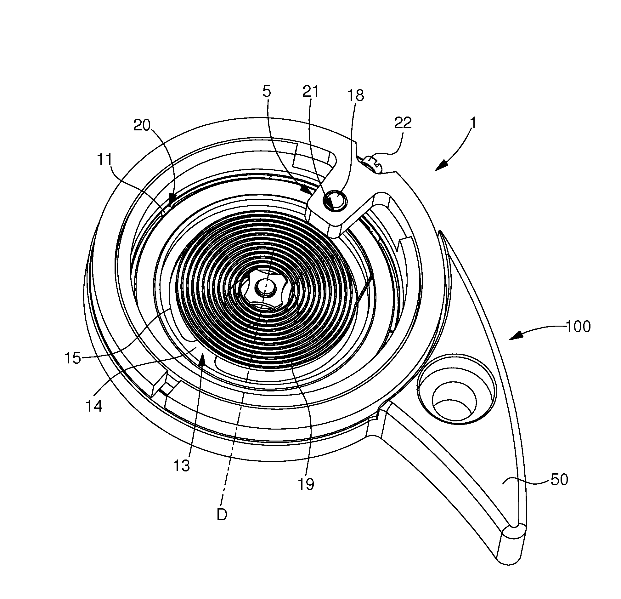
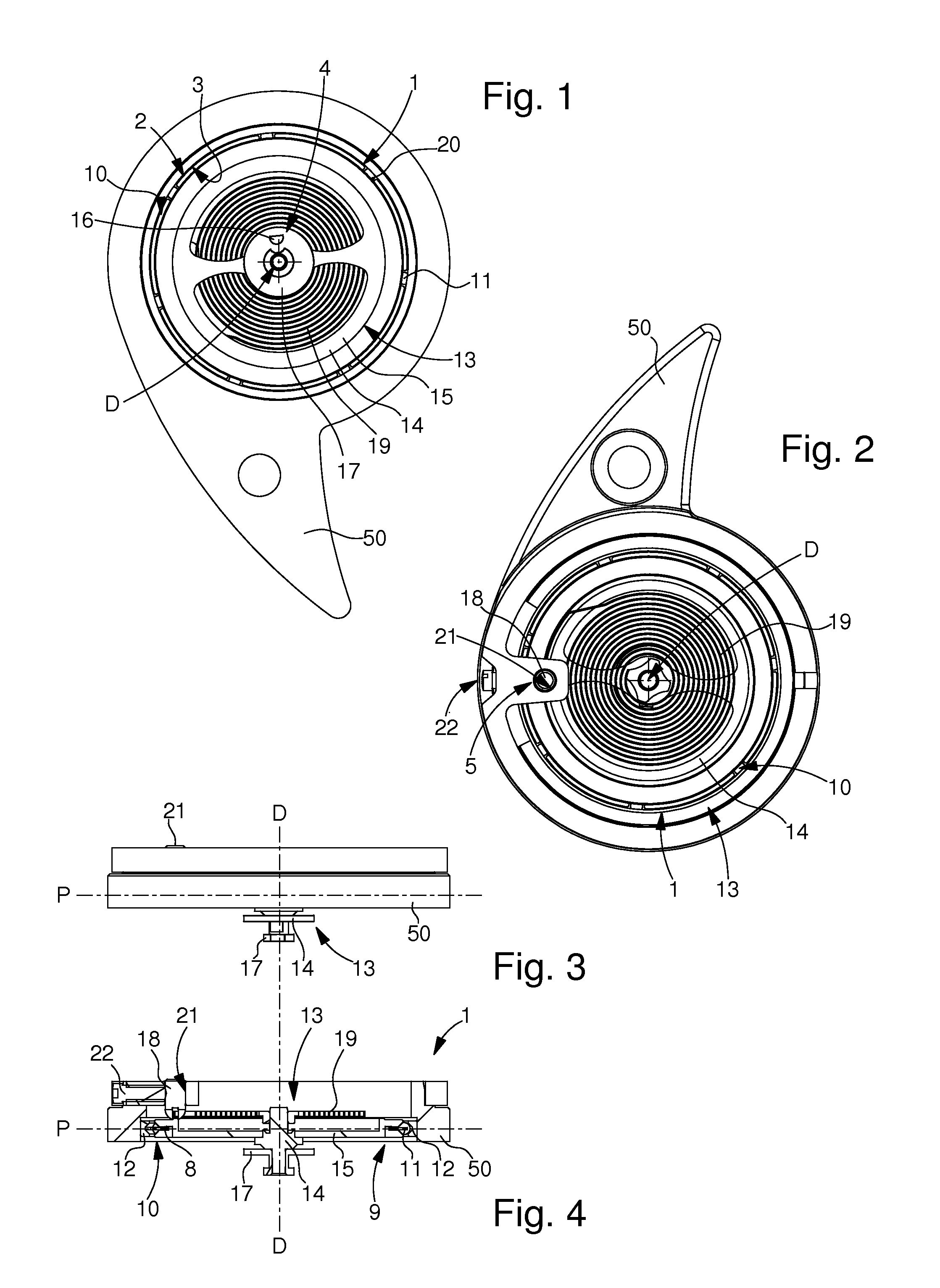
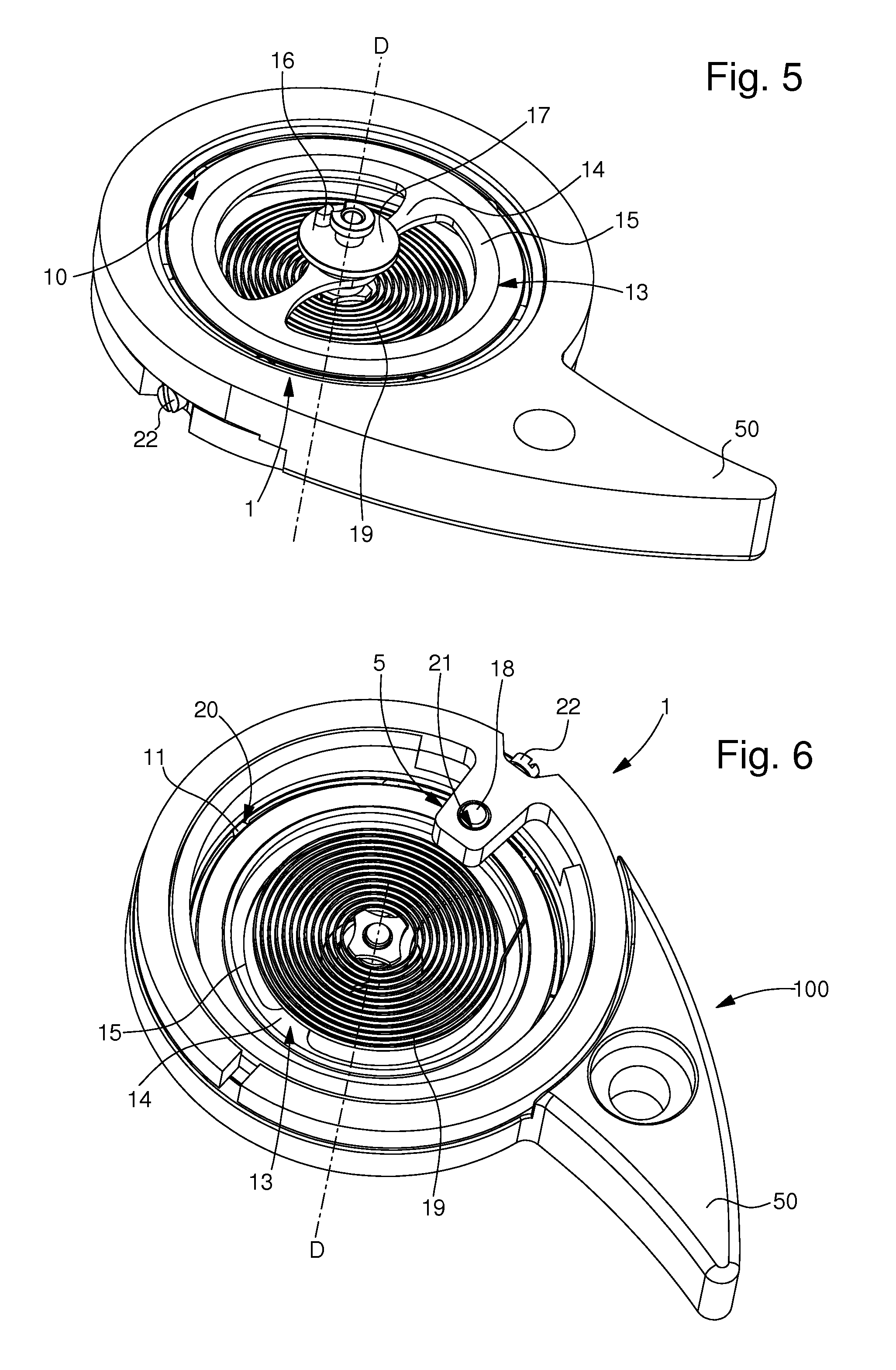
[0040]As seen in the Figures, the invention concerns a timepiece wheel set 1. This wheel set 1 is of the type with lower inertia and / or greater angular velocity and is selected from among an oscillator mechanism, an escapement mechanism, a display mechanism, a time-setting mechanism, a striking mechanism, a calendar mechanism, a chronograph mechanism, a counter mechanism or a flyback mechanism. This is by no means an exhaustive list of the possibilities of the invention, but sets out the preferred applications. Wheel set 1 is arranged to pivot about a pivot axis D.

[0041]According to the invention, wheel set 1 includes a first guide surface 2, which is arranged to cooperate in a complementary manner, directly or indirectly, with a second guide surface 3 associated with a bridge 50 for pivotally mounting wheel set 1 relative to bridge 50 about a pivot axis D.

[0042]Acco...


PUM


Abstract

Timepiece wheel set (1) including a first guide surface (2) cooperating with a second guide surface (3) associated with a bridge (50), for pivotally mounting the wheel set (1) relative to the bridge (50) about an axis (D). The first guide surface (2) is a single surface, located on a median plane (P) of said wheel set (1), orthogonal to this axis (D), for holding the wheel set (1) careened or in a cantilever arrangement relative to this bridge (50), and the wheel set (1) is free of any guide arbours on either side of this guide surface (2).This wheel set (1) forms a ball bearing (10) wherein the first guide surface (2) forms an internal raceway (9) for balls (11) and wherein an external ball race (12) mounted on the bridge (50) includes the second guide surface (3) forming an external raceway for the balls (11).

Description

CROSS REFERENCE TO RELATED APPLICATIONS[0001]This is a National Stage of International Application No. PCT / EP2011 / 070670 filed Nov. 22, 2011, claiming priority based on European Patent Application No. 10195928.6filed Dec. 20, 2010, the contents of all of which are incorporated herein by reference in their entirety.FIELD OF THE INVENTION[0002]The invention concerns a timepiece wheel set, selected from among an oscillator mechanism, an escapement mechanism, a display mechanism, a time-setting mechanism, a calendar mechanism, a chronograph mechanism, a counter mechanism or a flyback mechanism, wherein said wheel set includes a first guide surface arranged to cooperate in a complementary manner, directly or indirectly with a second guide surface associated with a bridge, for pivotably mounting said wheel set relative to said bridge about a pivot axis.[0003]The invention also concerns a timepiece movement including at least one bridge and at least one such wheel set.[0004]The invention a...

Claims


Application Information

Patent Timeline
Patent Type & Authority Patents(United States)
IPC IPC(8): G04B15/00G04B15/14G04B17/06G04B31/012
CPCG04B15/14G04B17/06G04B31/0123G04B31/012
Inventor BECCIA, VINCENT
Owner BLANCPAIN SA
Why Eureka
Try Eureka