Coning and threading machine for high-pressure tubing

a technology of high-pressure tubing and threading machine, which is applied in the direction of tube shearing machine, threaded fastener, manufacturing tool, etc., can solve the problem of significant manipulation of high-pressure tubing being machined

Inactive Publication Date: 2015-04-28
MAXPRO TECH
View PDF8 Cites 7 Cited by
  • Summary
  • Abstract
  • Description
  • Claims
  • Application Information

AI Technical Summary

Benefits of technology

[0001]The present invention is directed to a device used in threading thick-walled tubing. More particularly, the present invention is directed to a machine for coning and thr...

Problems solved by technology

This requires significant manipulation of the high-pressure tubing being machined which is parti...

Method used


Image

  • Coning and threading machine for high-pressure tubing
  • Coning and threading machine for high-pressure tubing
  • Coning and threading machine for high-pressure tubing

Examples


Embodiment Construction

)

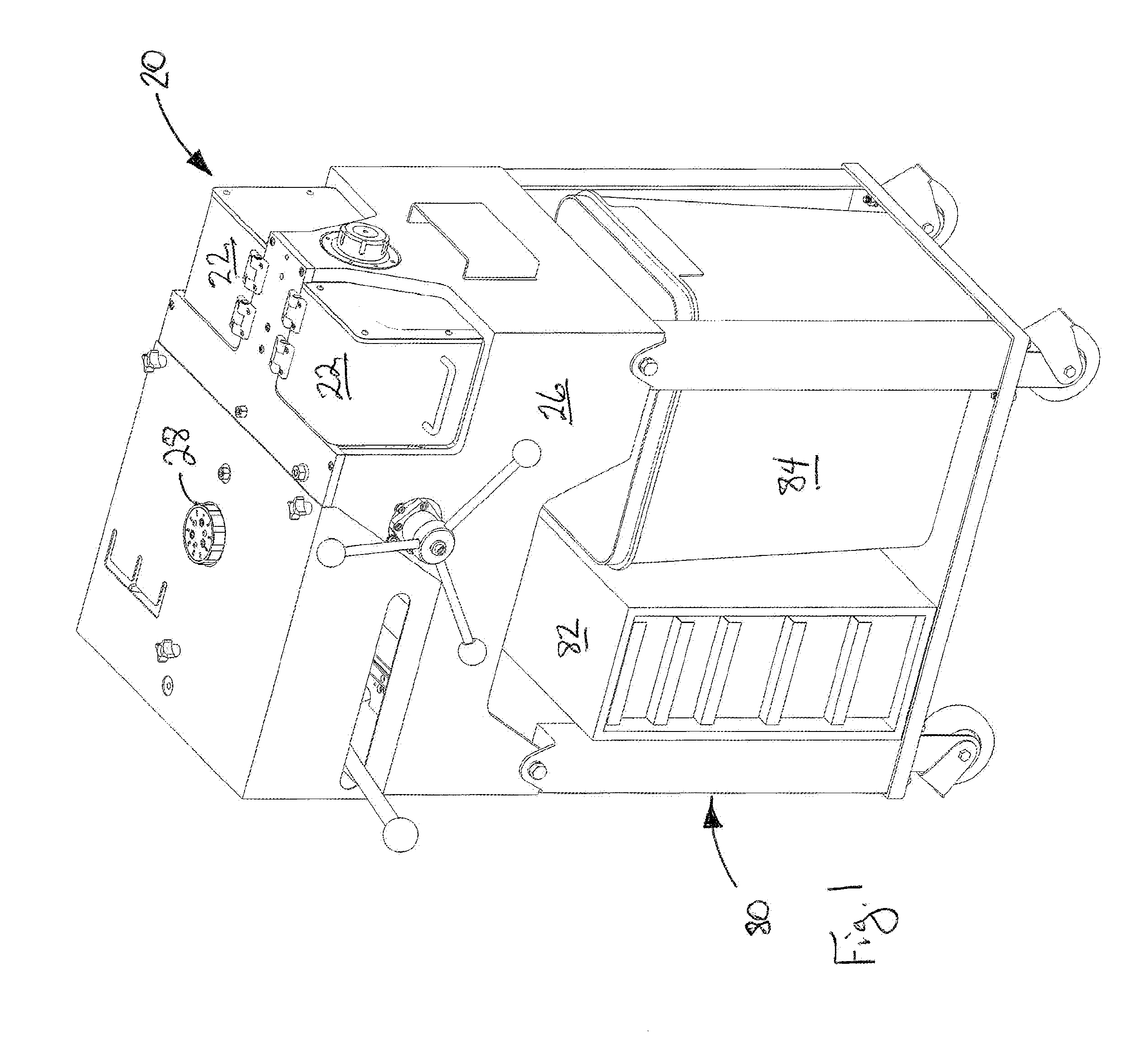
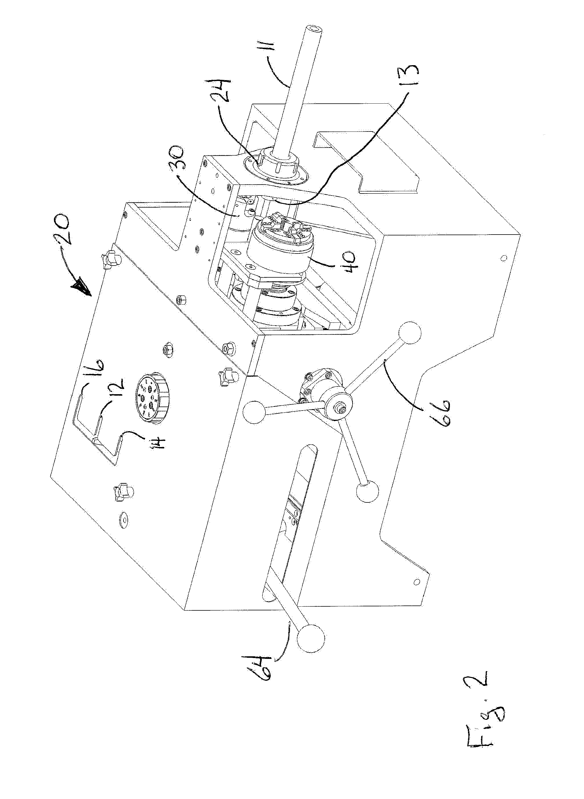
[0016]A first embodiment of the coning and threading machine of the present invention is depicted in FIGS. 1-4 generally at 20. Coning and threading machine 20 (FIG. 2) is preferably mounting on cart 80 (FIG. 1) with storage for a tool box 82 and a place for coolant bucket 84. Shown in FIG. 1, but omitted for clarity from the remaining figures, are a pair of transparent shields 22 pivotally mounted to housing 26 which allow the operator to observe the coning and threading operations safely, protecting her / him from coolant and flying chips removed from the workpiece.

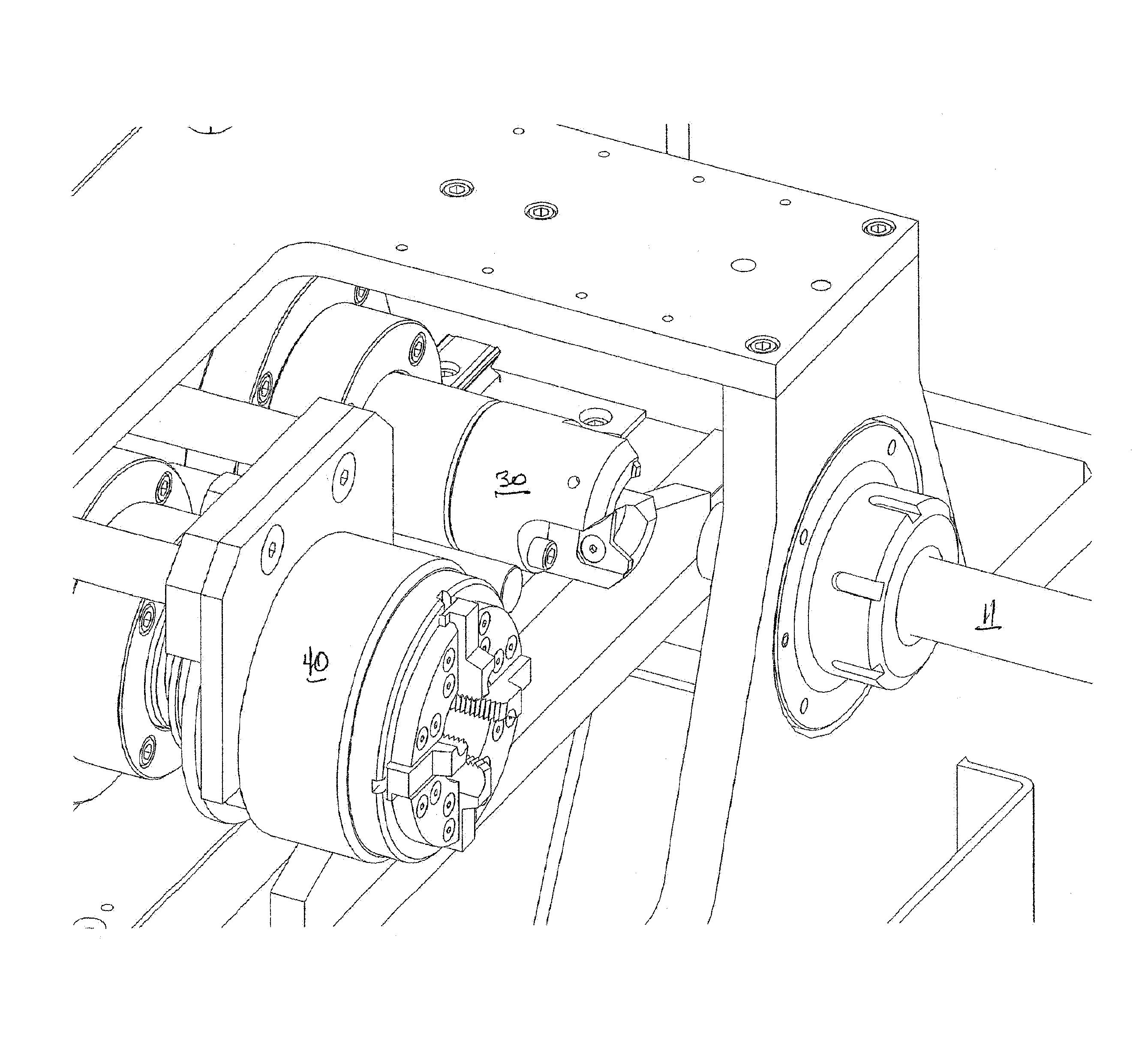
[0017]As best seen in FIG. 7, coning head 30 and threading head 40 are mounted on carriage 50 which is mounted for lateral movement on dovetail rails 60L and 60R by followers 62L and 62R, respectively. Movement is effected by manipulation of translating handle 64 (FIG. 2) between a center position 12 for insertion of workpiece 11 in collet 24, a forward position for coning 14 in which coning head 30 is aligned with workp...


PUM

PropertyMeasurementUnit
Pressureaaaaaaaaaa
Diameteraaaaaaaaaa
Lengthaaaaaaaaaa

Abstract

A machine permits an end of a thick-walled, high-pressure tubing to be chucked in a collet one time, coned, faced and threaded, using a coning head and threading head which are mounted on a carriage which can be translated laterally between three positions and the coning and threading heads parallel to the longitudinal axis of the workpiece to complete the coning and threading operations.

Description

BACKGROUND AND SUMMARY OF THE INVENTION[0001]The present invention is directed to a device used in threading thick-walled tubing. More particularly, the present invention is directed to a machine for coning and threading the end of a length of high-pressure (>10,000 psi) tubing to enable it to be joined to an adjacent length of tubing or fittings including tees, crosses, elbows, and valves.[0002]The present invention relates to preparing high-pressure tubing (generally stainless steel) for connection using a collar by coning and affixing, by way of example and not limitation, a left-handed thread. High-pressure tubing is used in support equipment for the oil and gas drilling industry, and is also utilized in water jet, water blast, and other industries as well. While coning and threading is fairly easy for ¼″ OD tube stock, a machine is needed for tube OD's from ⅜″ though 1″. The coning and threading machine of the present invention provides for coning, facing, and threading from...

Claims


Application Information

Patent Timeline
IPC IPC(8): B23P23/02B23G1/22B23G1/08B23G1/24B23Q11/00B23Q11/08B23Q11/10
CPCB23P23/02B23G1/08B23Q11/0067B23Q11/0891B23Q11/1015B23G1/24B23G1/22B23G2240/12B23G2240/08Y10T409/30392Y10T409/304032Y10T409/300448Y10T29/5199Y10T29/5174Y10T409/300504Y10T409/304088B23B5/16
Inventor SOLTYS, GREGORY B.BILSKI, BRAD R.
Owner MAXPRO TECH
Why Eureka
Try Eureka