
Fuel cell

a fuel cell and cell plane technology, applied in the field of fuel cells, can solve problems such as deterioration of the performance of fuel cells, and achieve the effects of improving startup properties, suppressing thermal diffusion of inside and outside of fuel cells, and reducing the number of cells

Inactive Publication Date: 2015-05-05
TOYOTA JIDOSHA KK +1
View PDF10 Cites 0 Cited by
  • Summary
  • Abstract
  • Description
  • Claims
  • Application Information

AI Technical Summary

Benefits of technology

The present invention is a fuel cell with an insulating portion that helps achieve the appropriate insulating properties needed for safe and efficient operation. The fuel cell has low thermal conductivity and high porosity, resulting in suppression of thermal diffusion and correction of temperature non-uniformity, which improves startup properties and ensures high reliability and performance.

Problems solved by technology

This temperature drop might cause the deterioration of the performance of the fuel cell.

Method used


Image

  • Fuel cell
  • Fuel cell
  • Fuel cell

Examples


Embodiment Construction

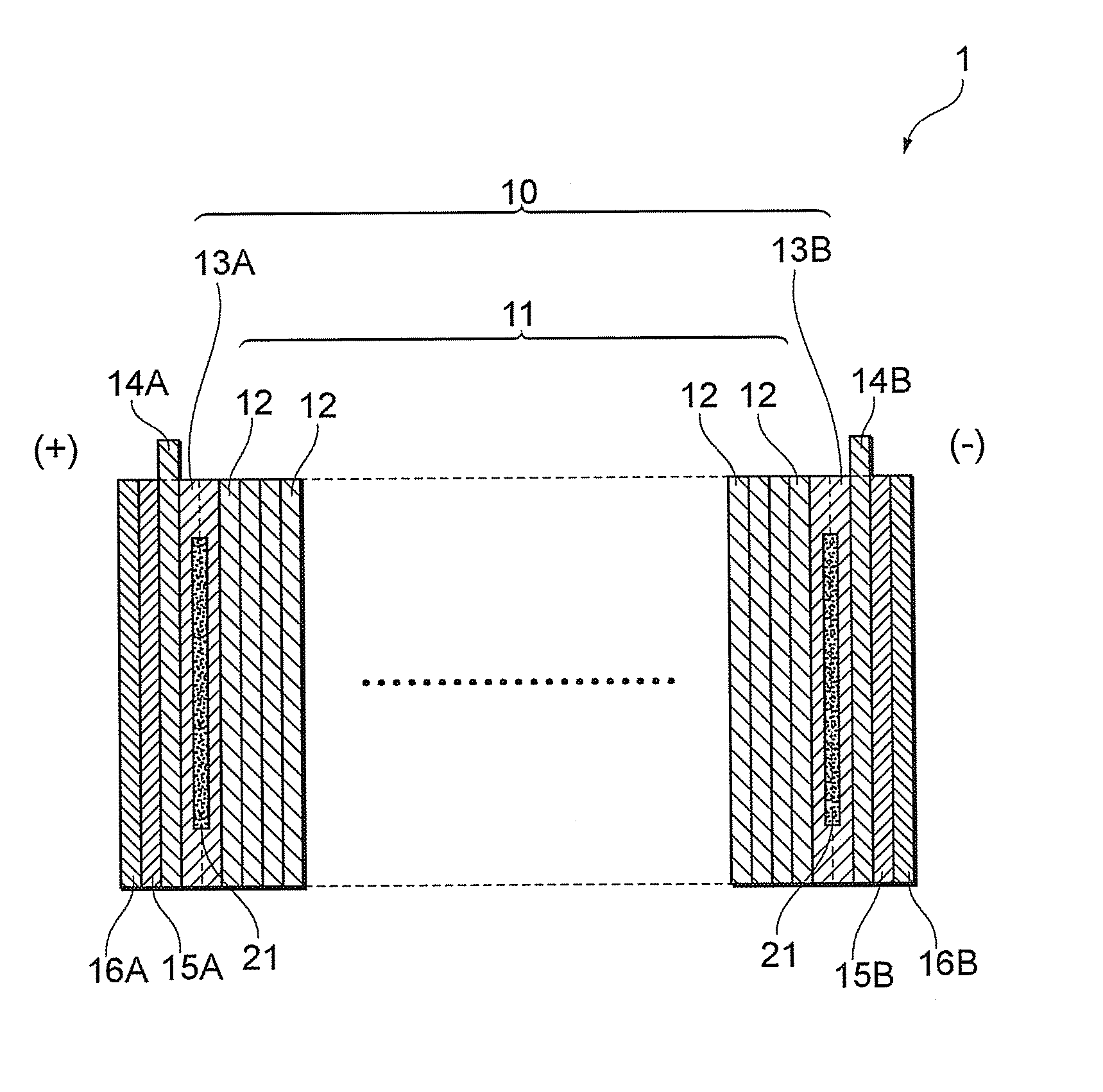
[0029]Next, fuel cells according to preferable embodiments of the present invention will be described with reference to the drawings. It is to be noted that the embodiments described as follows are illustrations for explaining the present invention, and the present invention is not limited only to these embodiments. Therefore, the present invention can be implemented in various configurations without departing from the scope of the present invention.

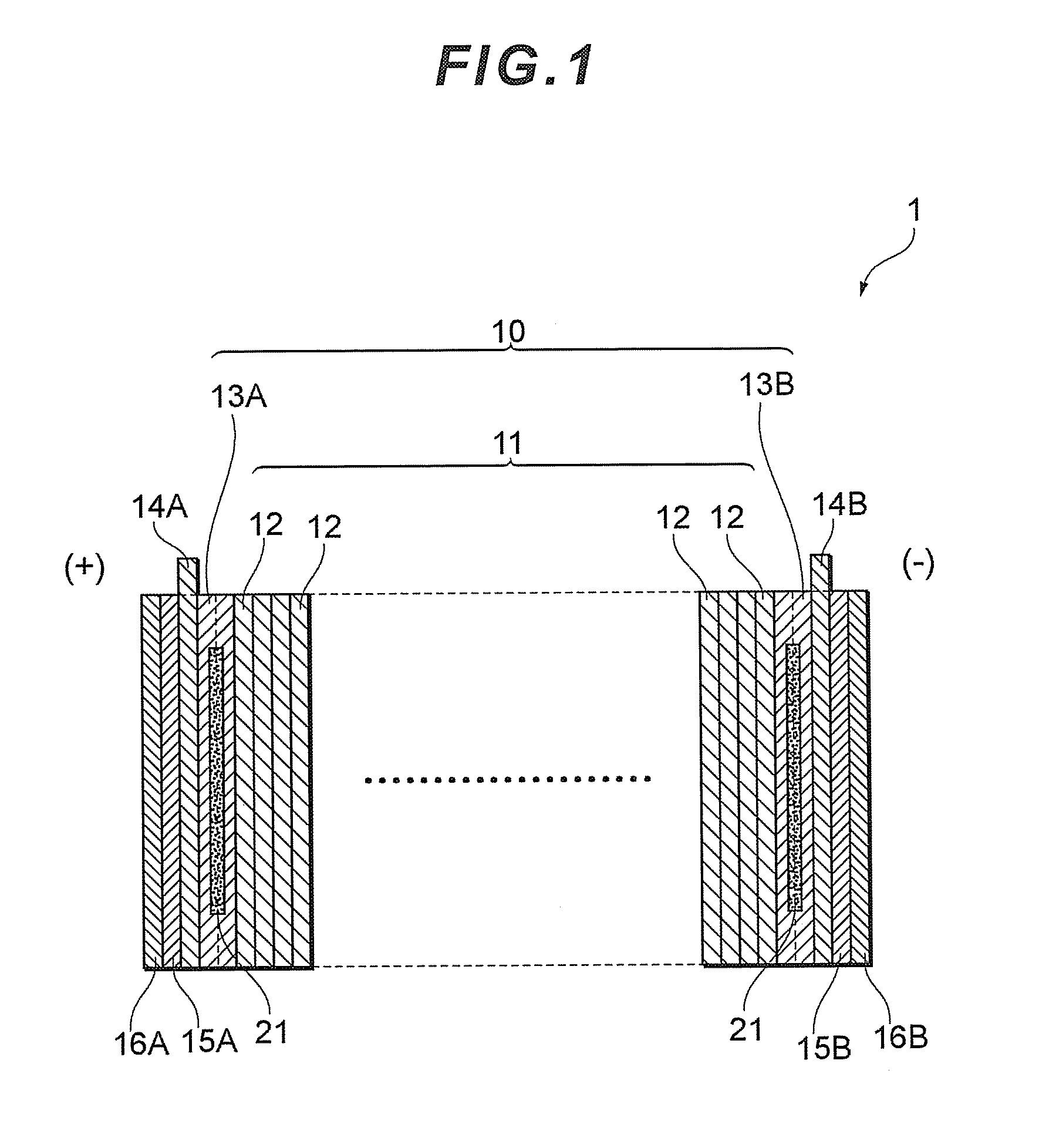
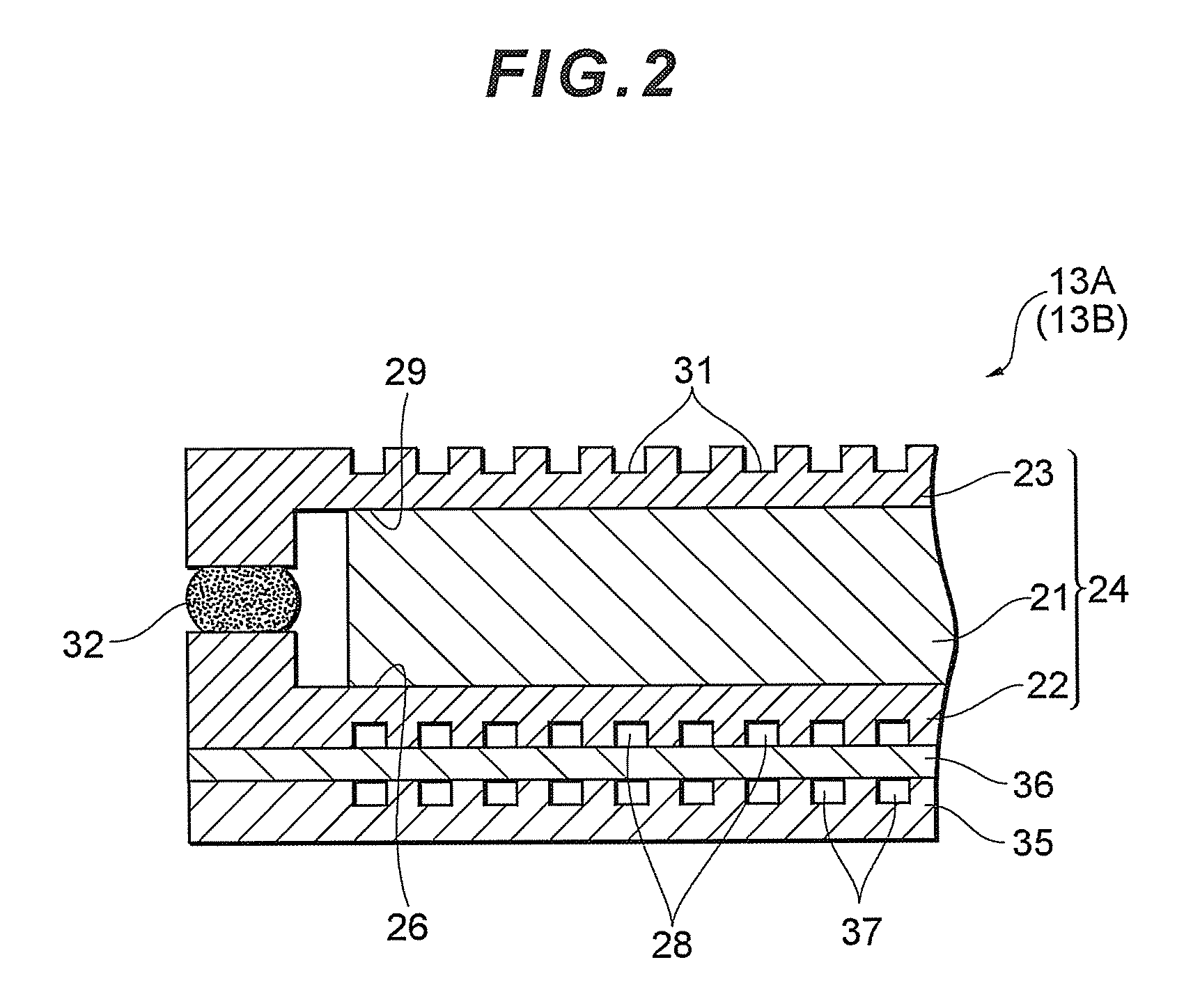
[0030]FIG. 1 is a sectional view schematically showing a fuel cell according to the embodiment of the present invention, FIG. 2 is a sectional view showing an enlarged part of an end cell disposed in the fuel cell shown in FIG. 1, and FIG. 3 is a plan view of an insulating portion which is a constituent element of the end cell disposed in the fuel cell shown in FIG. 1. It is to be noted that in the diagrams, for the easy understanding of the explanation, the thickness, size, enlargement / reduction ratio and the like of each member are not...


PUM

PropertyMeasurementUnit
porosityaaaaaaaaaa
electric resistanceaaaaaaaaaa

Abstract

There is disclosed a fuel cell in which an insulating material is disposed, whereby the thermal diffusion of the inside and outside of a fuel cell can be suppressed to suppress the deterioration of the performance of the fuel cell due to a temperature drop. Moreover, the physical properties of the insulating material are specified, whereby appropriate insulating properties required in the fuel cell can be obtained, and startup properties are improved. A fuel cell has a cell stack in which a plurality of unit cells are stacked, and terminal plates disposed on both sides of the cell stack in a cell stack direction thereof. The fuel cell comprises an insulating portion having an insulating material and holding plates which hold the insulating material from both the sides of the insulating material in the cell stack direction, the insulating material is held between the holding plates, and the insulating material has a thermal conductivity of 0.1 W / mK or less and a porosity of 70% or more.

Description

[0001]This is a 371 national phase application of PCT / JP2008 / 068867 filed 17 Oct. 2008, which claims priority to Japanese Patent Application No. 2007-272062 filed 19 Oct. 2007, the contents of which are incorporated herein by reference.TECHNICAL FIELD[0002]The present invention relates to a fuel cell having a cell stack in which a plurality of unit cells are stacked.BACKGROUND ART[0003]Heretofore, each unit cell of a usual fuel cell has had a structure in which separators are provided on both sides of a membrane electrode assembly (hereinafter referred to simply as the “MEA”) having an electrolyte membrane, an anode electrode disposed on one surface of the electrolyte membrane and a cathode electrode disposed on the other surface thereof. Moreover, in the fuel cell, a plurality of unit cells are stacked to obtain a cell stack, and at both ends of the cell stack in a cell stack direction, current collection plates (terminal plates), insulators, pressure plates, end plates and the lik...

Claims


Application Information

Patent Timeline
Patent Type & Authority Patents(United States)
IPC IPC(8): H01M8/24H01M8/02H01M8/04H01M8/10
CPCH01M8/2475H01M8/0271H01M8/04067H01M8/248H01M2008/1095Y02E60/50
Inventor YAMAMOTO, YOSHINORIYAMASHITA, KOICHIROWANO, TAKASHIMATSUSHIMA, RYOICHI
Owner TOYOTA JIDOSHA KK
Learn More