
Golf ball

a golf ball and ball technology, applied in the field of golf balls, can solve the problems of short flight golf balls traveling a great distance on middle or long iron shots, and have hardly been studied, so as to reduce the spin rate, increase the flight distance, and improve the effect of approach shots

Active Publication Date: 2015-05-12
SUMITOMO RUBBER IND LTD
View PDF19 Cites 0 Cited by
  • Summary
  • Abstract
  • Description
  • Claims
  • Application Information

AI Technical Summary

Benefits of technology

[0005]If the spin rate on approach shots is increased in order to stop the golf ball, the spin rate on middle or long iron shots also increases. As a result, the flight distance on middle or long iron shots becomes short. The present invention has been made in view of the above circumstances. An object of the present invention is to provide a golf ball traveling a great distance on middle or long iron shots and having an excellent controllability with a high spin rate on approach shots.
[0007]The polyurethane composition used in the present invention has higher rebound resilience for hardness thereof than the conventional polyurethane material. Thus, if the polyurethane composition used in the present invention is used as a material constituting the cover, it is possible to strike a balance between the controllability and flight distance.
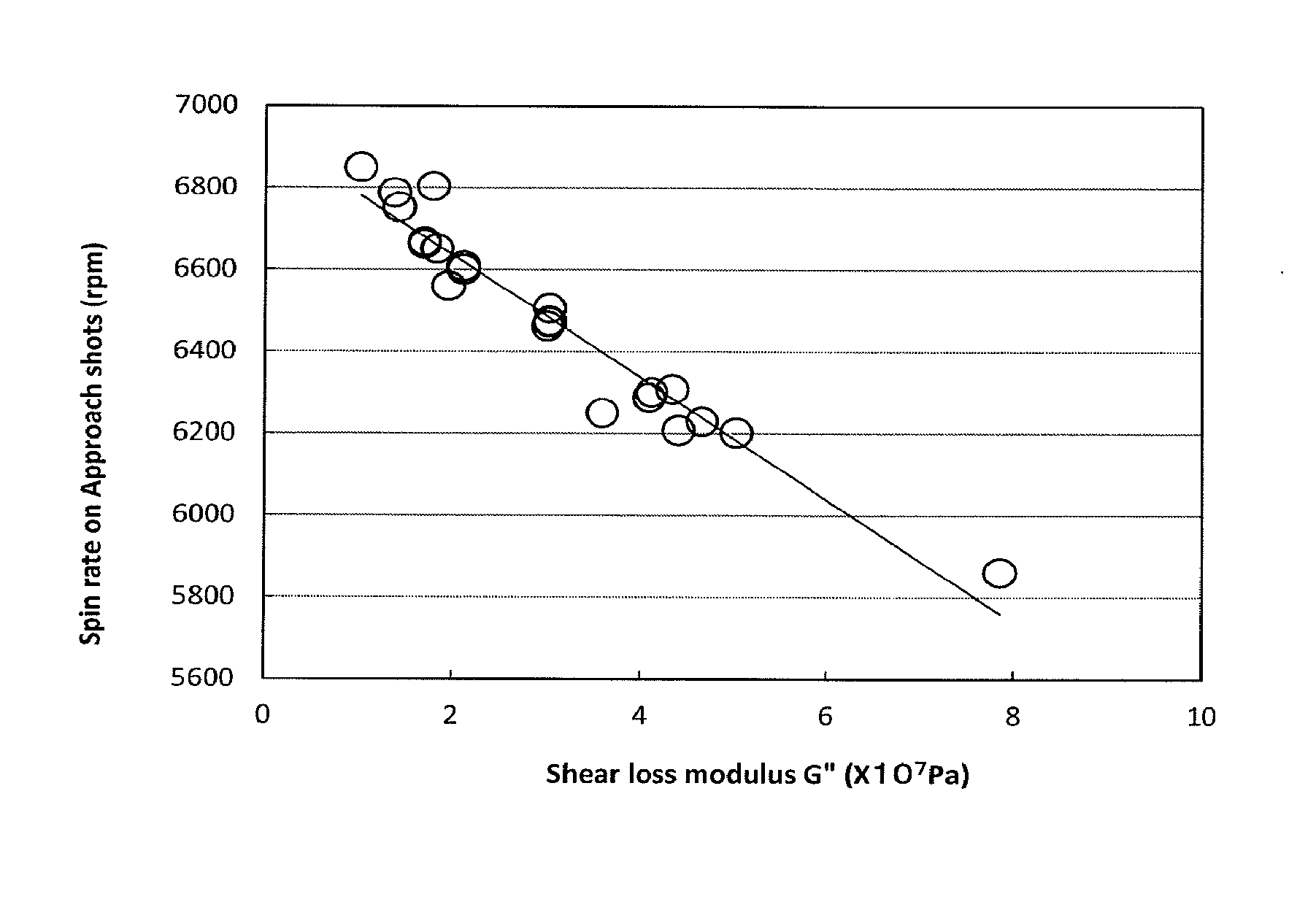
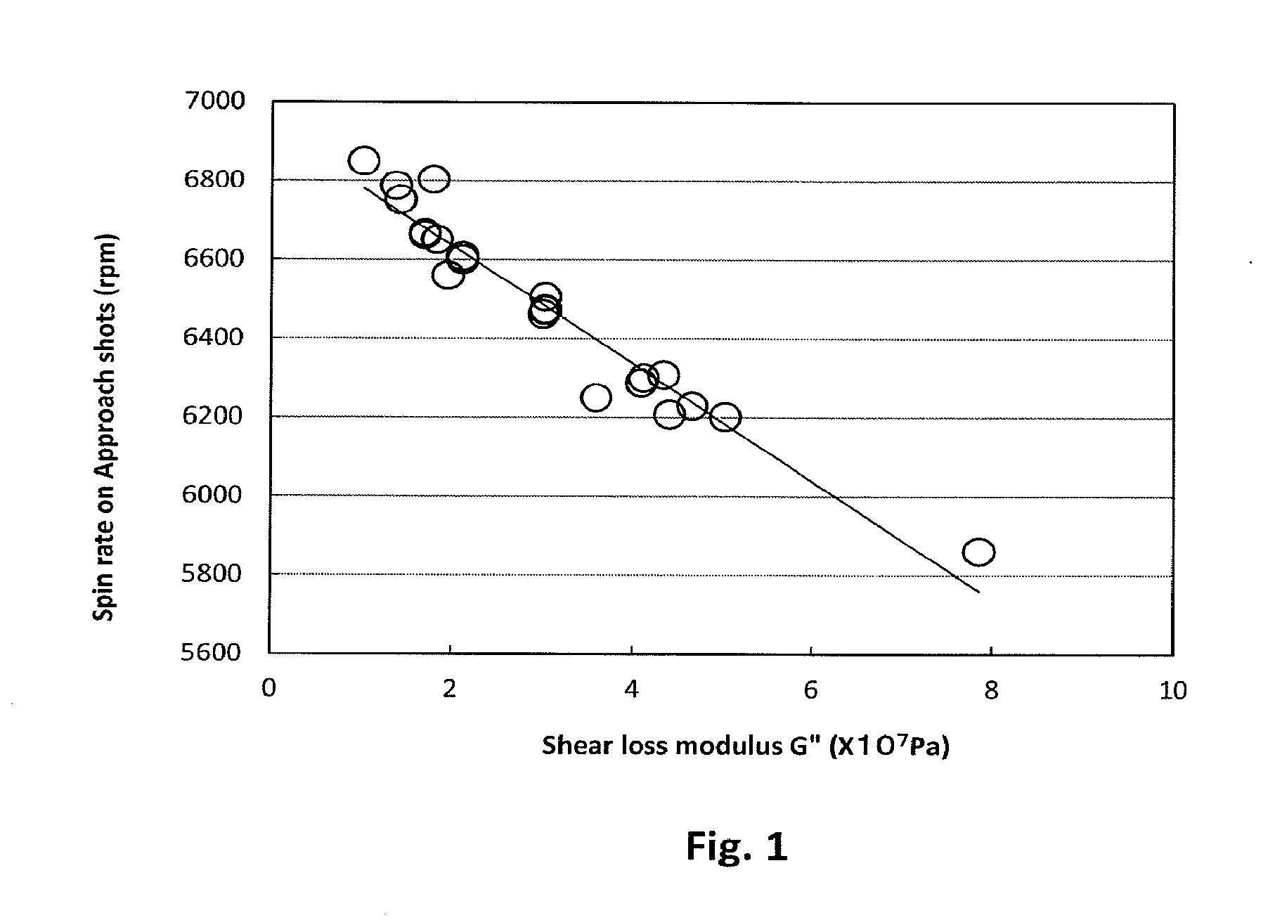
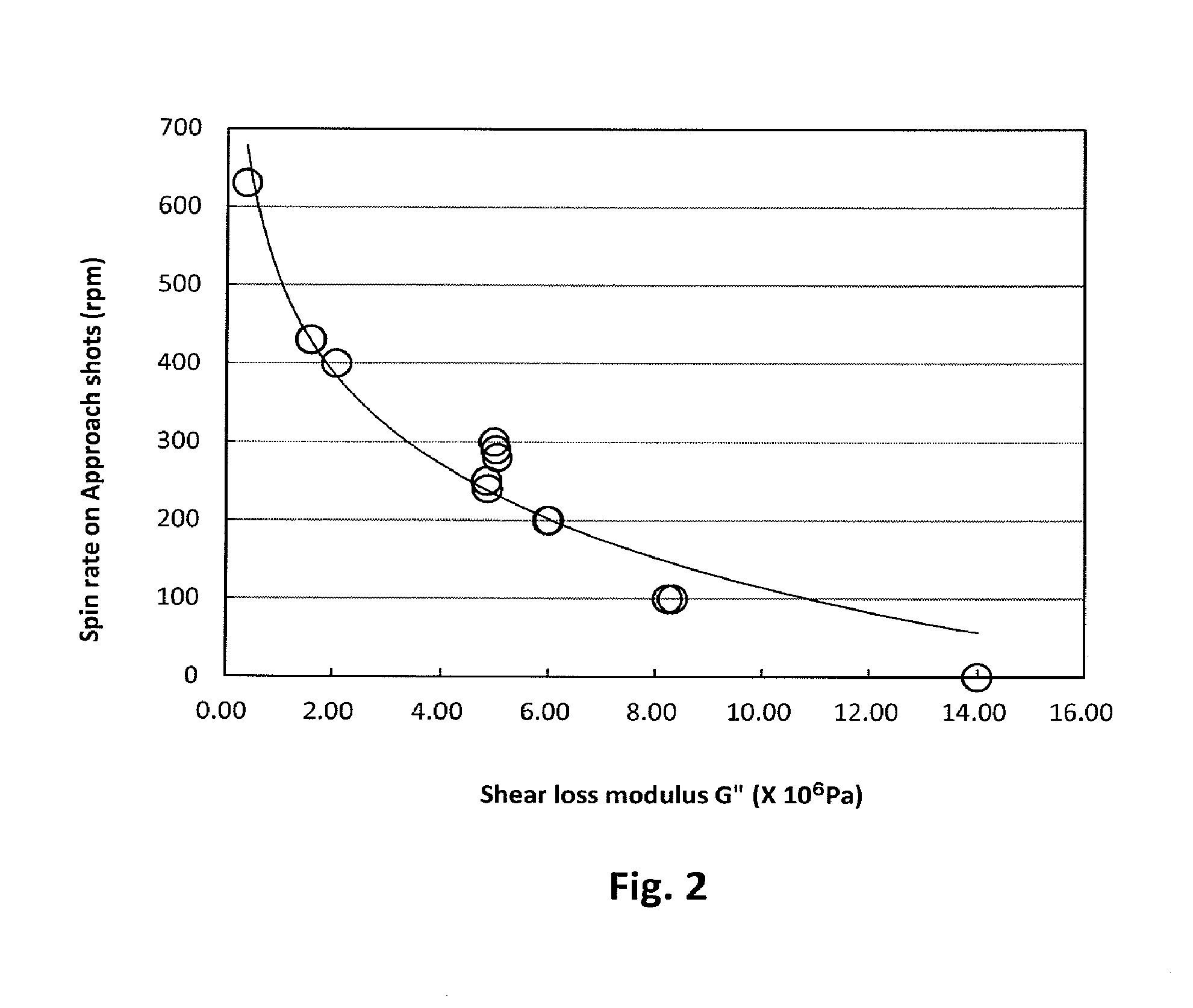
[0008]With respect to the deformation of the cover when hitting the golf ball, it is considered that the shear deformation is dominant on approach shots. Based on this hypothesis, the inventors of the present invention have studied characteristics of the polyurethane material, and found that the spin rate on approach shots correlates with the shear loss modulus G″ measured in a shear mode at the conditions of a temperature of 0° C. and oscillation frequency of 10 Hz using a dynamic viscoelasticity measuring apparatus. In the present invention, use of the polyurethane composition having a shear loss modulus G″ of 5.03×10⁶ Pa or less provides a golf ball with a high spin rate on approach shots. Concurrently, use of the polyurethane composition having rebound resilience of 54% or more improves the resilience of the golf ball, resulting in a greater flight distance.
[0010]The spherical core used in the present invention has a hardness distribution that R2 of a linear approximate curve determined by a least-squares method is 0.95 or more, when plotting JIS-C hardness measured at a center, a surface and at intervals of 2.5 mm from the center of the spherical core, versus distances from the center of the spherical core. Use of the spherical core having hardness distribution where the hardness increases linearly or almost linearly from the center of the core toward the surface thereof reduces the spin rate on middle or long iron shots, thereby providing a greater flight distance on middle or long iron shots.
[0011]According to the present invention, it is possible to provide a golf ball traveling a great distance on middle or long iron shots and having a high spin rate on approach shots.

Problems solved by technology

Although there are many proposals of golf ball traveling a great flight distance on driver shots, the golf balls traveling a great distance on middle or long iron shots have hardly been studied.
As a result, the flight distance on middle or long iron shots becomes short.

Method used


Image

  • Golf ball
  • Golf ball
  • Golf ball

Examples


preparation example 1

[0135]As a raw material, 1,4-bis(aminomethyl)cyclohexane (manufactured by Mitsubishi Gas Chemical Company, Inc.) having a trans-isomer / cis-isomer ratio of 93 / 7 determined by 13C-NMR was used to perform cold / hot two-stage phosgenation method under normal pressure. Specifically, a stirring rod, a thermometer, a phosgene inlet tube, a dropping funnel, and a condenser tube were attached to a flask, and the flask was charged with 400 parts by mass of ortho dichlorobenzene. While the flask was cooled with cold water, the temperature in the flask was lowered to 10° C. or below, and 280 parts by mass of phosgene was introduced thereinto from the phosgene inlet tube. The dropping funnel was charged with a mixed solution of 100 parts by mass of 1,4-bis(aminomethyl)cyclohexane and 500 parts by mass of ortho dichlorobenzene, and the mixed solution was added into the flask over 30 minutes. During this time, the temperature in the flask was maintained at 30° C. or below. After completion of the a...

preparation example 2

[0136]1,4-bis(isocyanatomethyl)cyclohexane was prepared in the same manner as Preparation Example 1 except that 1,4-bis(aminomethyl)cyclohexane (manufactured by Tokyo Chemical Industry Co., Ltd.) having a trans-isomer / cis-isomer ratio of 41 / 59 determined by 13C-NMR was used as a raw material. The obtained 1,4-bis(isocyanatomethyl)cyclohexane had a purity, determined by gas chromatography, of 99.9%, a hue of 5 in APHA, and a trans-isomer / cis-isomer ratio, determined by 13C-NMR, of 41 / 59. Hereinafter, 1,4-bis(isocyanatomethyl)cyclohexane having a trans-isomer / cis-isomer ratio of 41 / 59 is referred to as “BIC41”.

preparation example 3

[0137]BIC93 and BIC41 were mixed in a ratio of 86.5:13.5 to prepare 1,4-bis(isocyanatomethyl)cyclohexane having a trans-isomer / cis-isomer ratio of 86 / 14. Hereinafter, 1,4-bis(isocyanatomethyl)cyclohexane having a trans-isomer / cis-isomer ratio of 86 / 14 is referred to as “BIC86”.


PUM

PropertyMeasurementUnit
oscillation frequencyaaaaaaaaaa
temperatureaaaaaaaaaa
shear loss modulusaaaaaaaaaa

Abstract

The present invention provides a golf ball comprising a spherical core and at least one cover layer covering the spherical core, wherein the cover is formed from a polyurethane composition containing a polyurethane elastomer as a resin component, the polyurethane composition satisfying properties of rebound resilience of 54% or more and a shear loss modulus G″ of 5.03×10⁶ Pa or less when measured in a shear mode using a dynamic viscoelasticity measuring apparatus at the conditions of the temperature of 0° C., and the oscillation frequency of 10 Hz, and the spherical core has a hardness distribution that R2 of a linear approximate curve determined by a least-squares method is 0.95 or more, when plotting JIS-C hardness measured at a center, a surface and at intervals of 2.5 mm from the center of the spherical core, versus distances from the center of the spherical core.

Description

FIELD OF THE INVENTION[0001]The present invention relates to improvements of controllability on approach shots and flight distance on middle or long iron shots of a golf ball.DESCRIPTION OF THE RELATED ART[0002]Since 2010, a new groove regulation has entered in force in a professional golf world on clubs having a loft angle of 25° or more such as irons or wedges. This new regulation will be gradually applied to amateur golfers. Since this regulation reduces the spin rate on approach shots with short irons or wedges, it becomes difficult to stop the golf ball on the green. Based on this background, golf balls that have a higher spin rate and stop readily on the green are required.[0003]In order to stop a golf ball on the green on approach shots, for example, soft cover materials are used to increase a spin rate on approach shots (Japanese Patent Publication No. 2006-034740). Further, the inventors of the present invention have filed a Japanese patent application (published as Japanes...

Claims


Application Information

Patent Timeline
Patent Type & Authority Patents(United States)
IPC IPC(8): A63B37/12A63B37/14A63B37/00B29C43/14C08K5/098
CPCA63B37/0022A63B37/0063A63B37/0096A63B37/0003A63B37/0033A63B37/0061A63B37/0062A63B37/0064A63B37/0065B29C43/146A63B37/0051A63B37/0037C08K5/098A63B37/0077A63B37/00622A63B37/00621
Inventor TARAO, TOSHIYUKISHIGA, KAZUYOSHIMIKURA, CHIEMIFUSHIHARA, KAZUHISA
Owner SUMITOMO RUBBER IND LTD
Learn More