Apparatus for controlling hydrogen supply of fuel cell system and method for controlling the same

a fuel cell and apparatus technology, applied in the direction of electric control, battery/cell propulsion, machines/engines, etc., can solve the problems of jet pump, inability to generate the required recirculation flow, and the blower to become corrupted, so as to secure a sufficient level of hydrogen recirculation flow

Active Publication Date: 2015-05-12
HYUNDAI MOTOR CO LTD
View PDF9 Cites 6 Cited by
  • Summary
  • Abstract
  • Description
  • Claims
  • Application Information

AI Technical Summary

Benefits of technology

[0014]The present invention provides an apparatus for controlling hydrogen supply of a fuel cell system and a method for controlling the same, which can secure a sufficient level of hydrogen recirculation flow even in lower power fuel application situations in a typical recirculation system using an ejector.
[0015]The present invention also provides an apparatus for controlling hydrogen supply of a fuel cell system and a method for controlling the same, which can secure a required amount of recirculation flow by applying a simple configuration without a blower or other recirculation parts that are added to solve deficiency of the hydro recirculation flow during low power fuel applications in a typical recirculation system using an ejector
[0016]The present invention also provides an apparatus for controlling hydrogen supply of a fuel cell system and a method for controlling the same, which can improves the efficiency of a jet pump during low power fuel applications, by installing a proportional control solenoid on a hydrogen supply line connection part of the jet pump.
[0017]The present invention also provides an apparatus for controlling hydrogen supply of a fuel cell system and a method for controlling the same, which can provide a comfortable driving mode by removing noise that may be generated as a result of on / off control of a valve during a low power fuel application.
[0026]In another preferred exemplary embodiment, the peak and hold control method may include reducing noise by controlling a magnitude and an application time of a hold current value to divide the falling of a valve plunger into a plurality of stages and thus reducing an impulse generated by a collision at the bottom dead center.
[0027]In still another preferred exemplary embodiment, the peak and hold control method may include reducing noise by controlling a magnitude and an application time of a peak current value to control the position of a top dead center of a valve plunger and thus preventing a collision at the top dead center.

Problems solved by technology

On the other hand, in a system which adopts a blower like the one shown in FIG. 8, to recirculation hydrogen, must be equipped with a motor which is expensive, and bearings and other parts which may be easily corroded by condensation water of hydrogen recirculation gas thus, causing the blower to become corrupted.
Particularly, when water form from condensation is frozen, it may cause a rotor in the blower to seize, thereby requiring the rotor to be melted by a heater.
Furthermore, a jet pump, as shown in FIG. 7, cannot generate a required recirculation flow due to a limitation of recirculation hydrogen fuel which is an energy source that can be used when a system load is small.
That is, the jet pump is not able to generate the required recirculation flow when the load on the overall system is low due to the lack of hydrogen supplied to the system by the small load.
Accordingly, when there is a low load applied to the fuel cell system, thus requiring only a small amount of fuel to be used, the recirculation flow is not sufficient under the above operating conditions, and thus the operation state of the stack channel becomes worsened.
Also, the stack efficiency and durability may become worsened as a result as well.

Method used


Image

  • Apparatus for controlling hydrogen supply of fuel cell system and method for controlling the same
  • Apparatus for controlling hydrogen supply of fuel cell system and method for controlling the same
  • Apparatus for controlling hydrogen supply of fuel cell system and method for controlling the same

Examples


Embodiment Construction

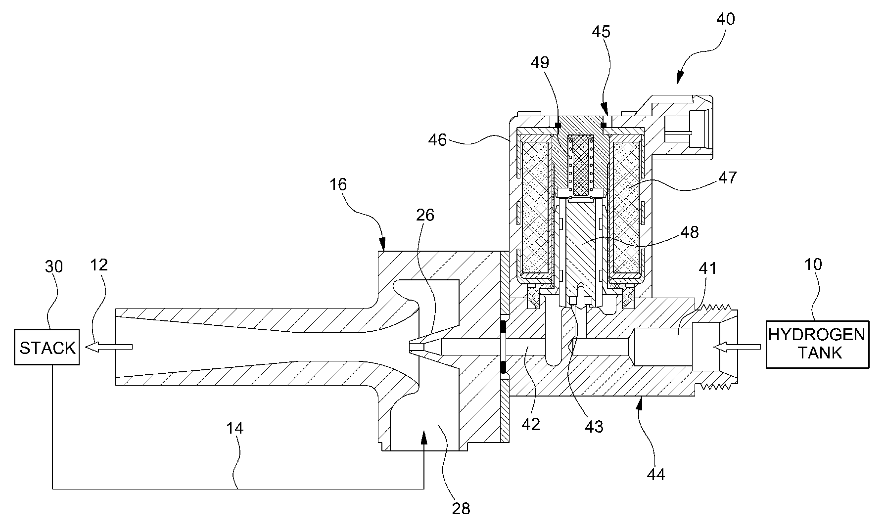
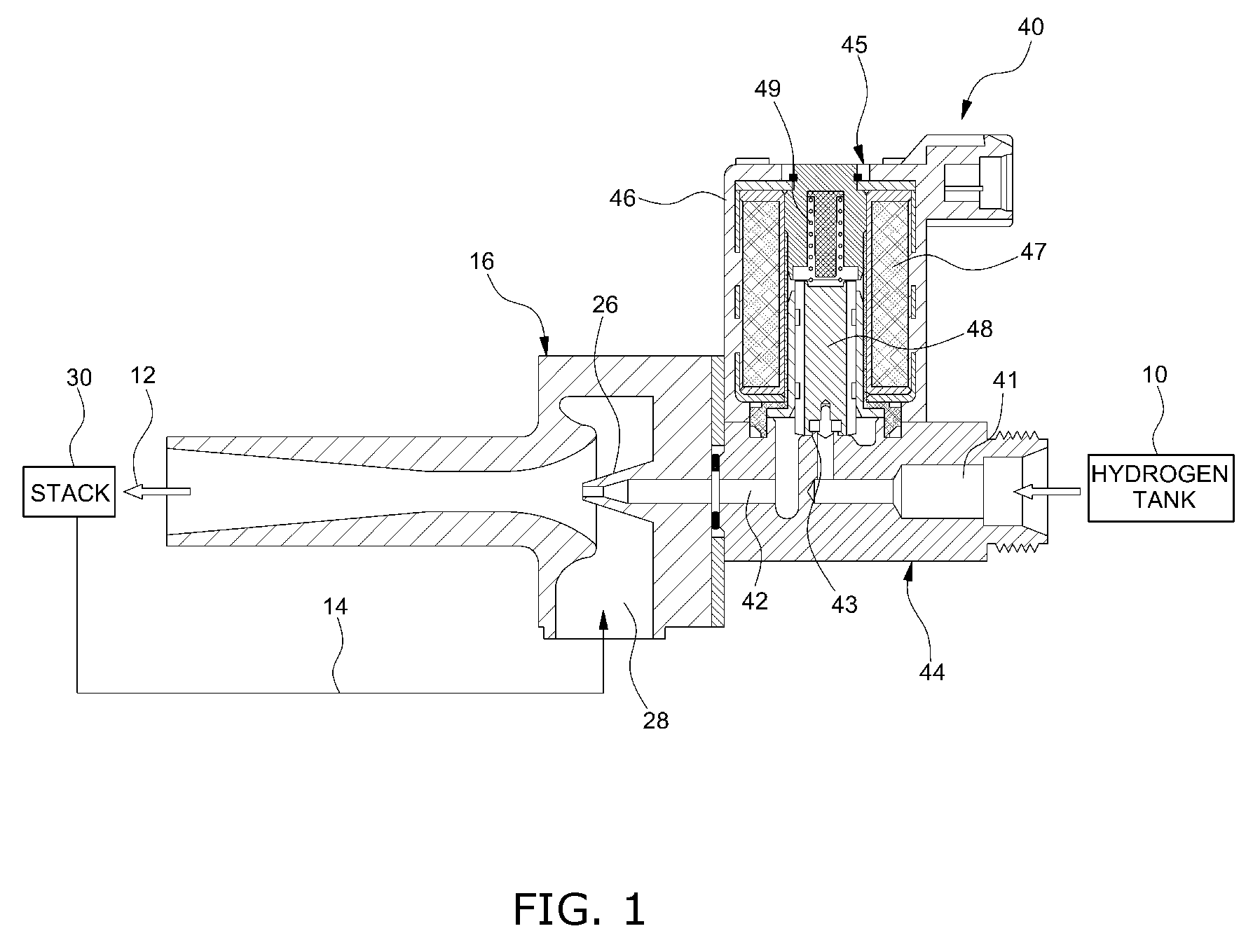
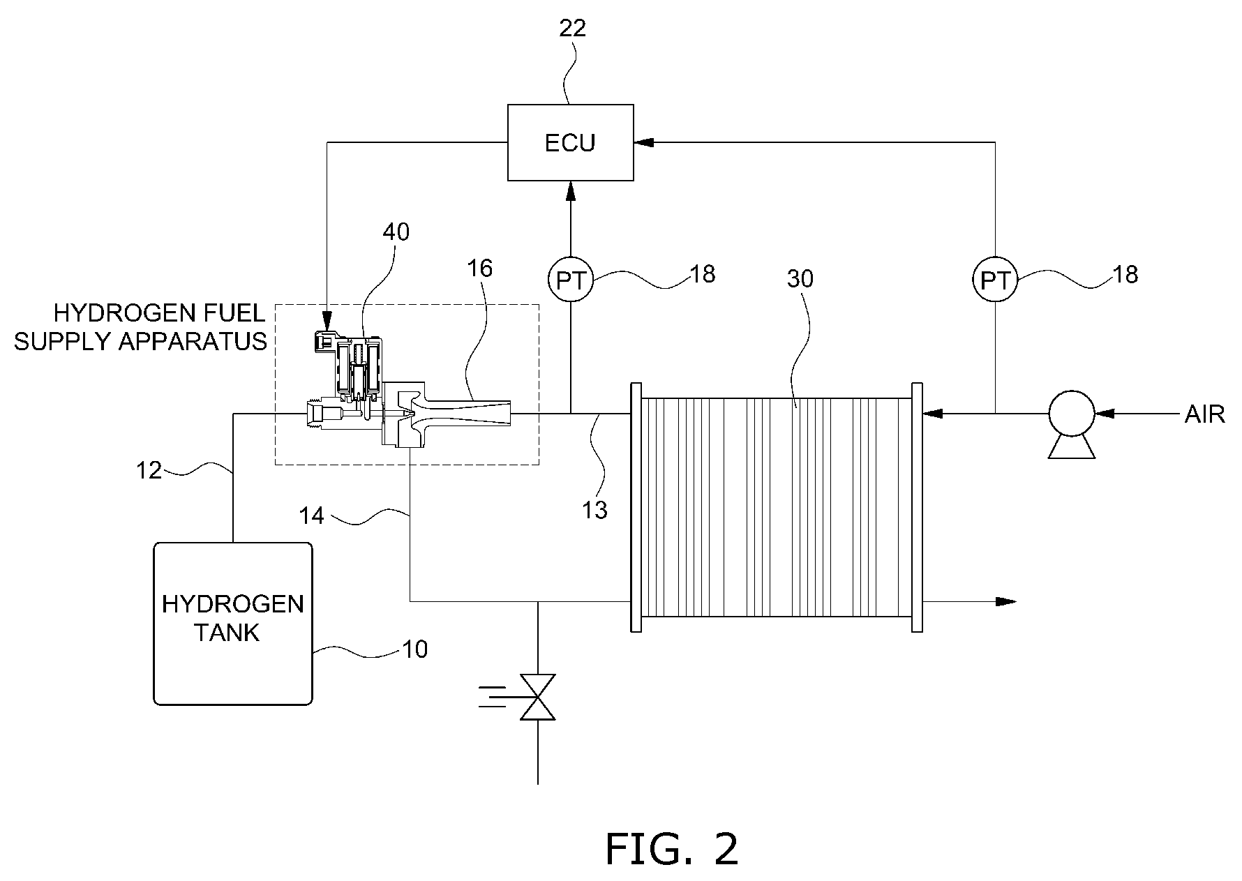
[0064]Hereinafter reference will now be made in detail to various embodiments of the present invention, examples of which are illustrated in the accompanying drawings and described below. While the invention will be described in conjunction with exemplary embodiments, it will be understood that present description is not intended to limit the invention to those exemplary embodiments. On the contrary, the invention is intended to cover not only the exemplary embodiments, but also various alternatives, modifications, equivalents and other embodiments, which may be included within the spirit and scope of the invention as defined by the appended claims.

[0065]It is understood that the term “vehicle” or “vehicular” or other similar term as used herein is inclusive of motor vehicles in general such as passenger automobiles including sports utility vehicles (SUV), buses, trucks, various commercial vehicles, watercraft including a variety of boats and ships, aircraft, and the like, and inclu...


PUM

PropertyMeasurementUnit
current poweraaaaaaaaaa
pressureaaaaaaaaaa
peak currentaaaaaaaaaa

Abstract

The present invention provides an apparatus for controlling hydrogen supply of a fuel cell system and a method for controlling the same. The apparatus includes a jet pump, a proportional control solenoid valve, and a controller. The jet pump is disposed at the side of an inlet of a fuel cell stack and performs supply and recirculation of hydrogen into the fuel cell stack. The proportional control solenoid valve is connected to a hydrogen supply line and fluidly communicates with a nozzle inlet of the jet pump to control the hydrogen supply to the jet pump. The controller controls an operation of the proportional control solenoid valve according to a power of the fuel cell system. Here, the controller controls the operation of the proportional control solenoid valve according to a pulse flow control method at a low power section in which a current power is lower than a predetermined reference power.

Description

CROSS-REFERENCE TO RELATED APPLICATION[0001]This application claims under 35 U.S.C. §119(a) the benefit of Korean Patent Application No. 10-2011-0055814 filed Jun. 9, 2011, the entire contents of which are incorporated herein by reference.BACKGROUND[0002](a) Technical Field[0003]The present invention relates to an apparatus for controlling hydrogen supply of a fuel cell system and a method for controlling the same. More particularly, it relates to an apparatus for controlling hydrogen supply of a fuel cell system and a method for controlling the same, which can achieve a function of controlling hydrogen supply flow and anode recirculation performance necessary for a fuel cell in conjunction with a jet pump, by utilizing the flow control characteristics of a proportional control solenoid valve for control of hydrogen fuel supply to a fuel cell stack, and controlling the operation of the proportional control solenoid valve using a pulse flow control method together with a proportional...

Claims


Application Information

Patent Timeline
Patent Type & Authority Patents(United States)
IPC IPC(8): H01M8/04B60L1/00B60L11/18F02D41/00F02M63/00
CPCH01M8/04992H01M8/04097H01M8/04388H01M8/04604H01M8/04619H01M8/04798F02M63/0017B60L1/003B60L11/1898F02D41/0027H01M2250/20Y02E60/50Y02T90/16Y02T90/34Y02T90/32B60L50/72Y02T90/40F16K31/06G05D7/06H01M8/04
Inventor NOH, YONG GYUJUNG, SE KWONBAE, HO JUNE
Owner HYUNDAI MOTOR CO LTD
Why Eureka
Try Eureka