
Parallel low and asymmetric rate Reed Solomon coding

a reed solomon and low rate technology, applied in the field of parallel low and asymmetric rate reed solomon coding, can solve the problems of high cost, large size, monetary cost, power consumption, and the introduction of data errors at a much lower frequency

Active Publication Date: 2015-05-12
ALTERA CORP
View PDF28 Cites 1 Cited by
  • Summary
  • Abstract
  • Description
  • Claims
  • Application Information

AI Technical Summary

Benefits of technology

The patent describes systems, devices, and methods for producing a recovered codeword from a received codeword. The system includes a receiver circuitry to receive the codeword, a decoding circuitry to asymmetrically process the received codeword, and a data recovery circuitry to modify the received codeword based on a plurality of error values. The decoding circuitry includes a syndrome computation circuitry to produce a plurality of error values and an error locator polynomial circuitry to process the plurality of error values and produce an error evaluator polynomial. The error search and calculation circuitry performs an error search and calculation in a plurality of stages to output a corresponding plurality of p error values. The receiver circuitry delays the output of the received codeword for a number of clock cycles. The technical effects of the patent include improved error recovery and increased efficiency in processing received codewords.

Problems solved by technology

However, decoder implementations for such codes are expensive in terms of an amount of required logic, e.g., in terms of a required number of adaptive look-up tables (ALUTs), and hence, in terms of a size, monetary cost, and power consumption.
Such networks typically introduce data errors at a frequency much lower than an error correction capacity of a corresponding error correction code.
However, actual error rates experienced on OTN networks are in the range of 10−9 to 10−15 errors per symbol.
Pipelining typically requires a large amount of duplicative circuitry.
Finite-field dividers, in particular, are typically duplicated in decoder implementations for high speed networks and often result in a substantial amount of required logic circuitry.

Method used


Image

  • Parallel low and asymmetric rate Reed Solomon coding
  • Parallel low and asymmetric rate Reed Solomon coding
  • Parallel low and asymmetric rate Reed Solomon coding

Examples


Embodiment Construction

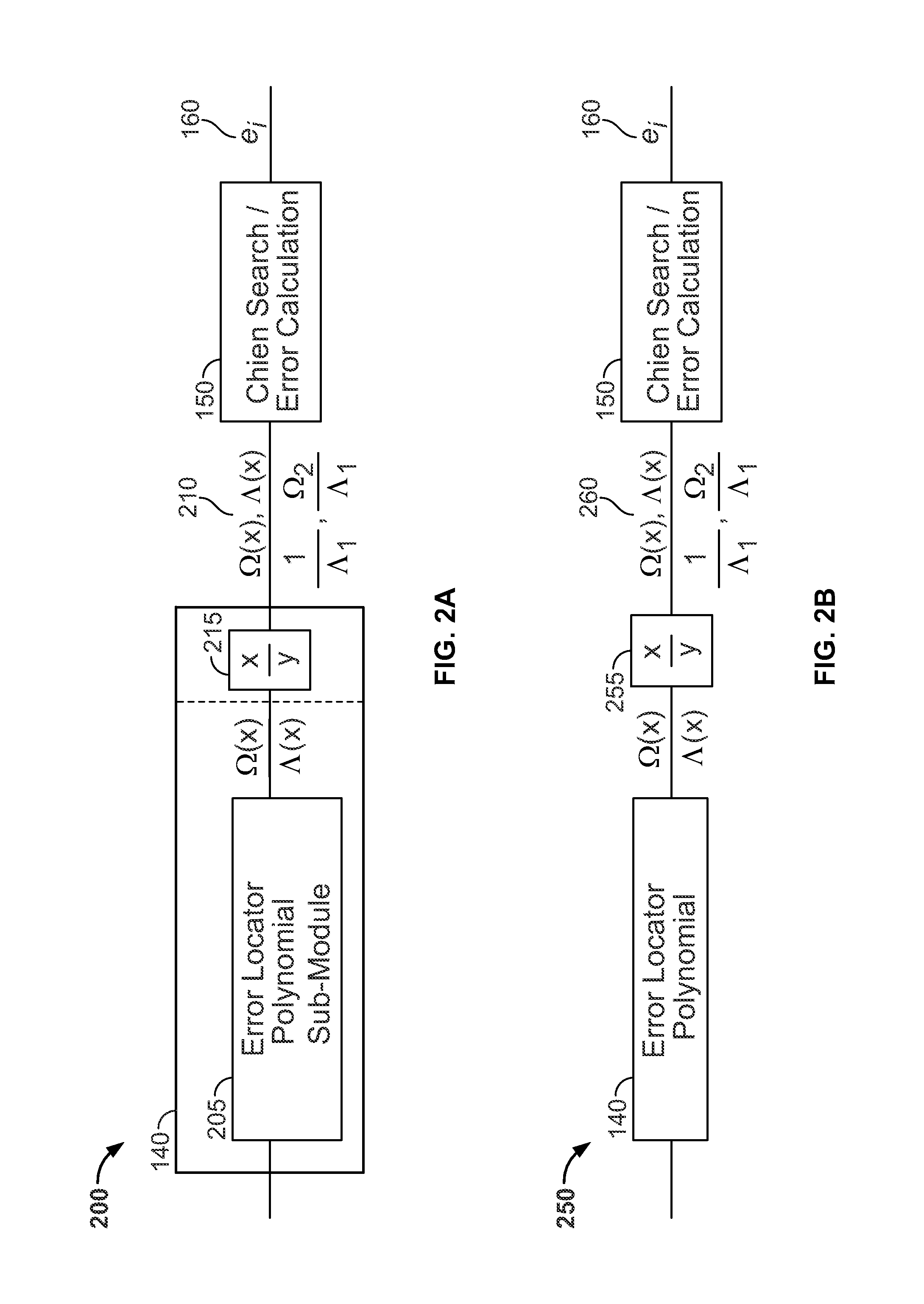
[0024]Disclosed herein are methods, systems, and apparatus for implementing Reed-Solomon decoders, and other types of decoders, in a network environment. The disclosed methods, systems, and apparatus advantageously reduce a number of ALUTs required for a decoder implementation in a pipelined architecture. As described herein, such advantages are achieved in various arrangements by using an asymmetric decoder (i.e., a decoder that is functional to correct less than a maximum number of correctable codewords in a Reed-Solomon codeword) and / or by reducing or eliminating a number of finite-field dividers required per pipeline stage in a decoder implementation.

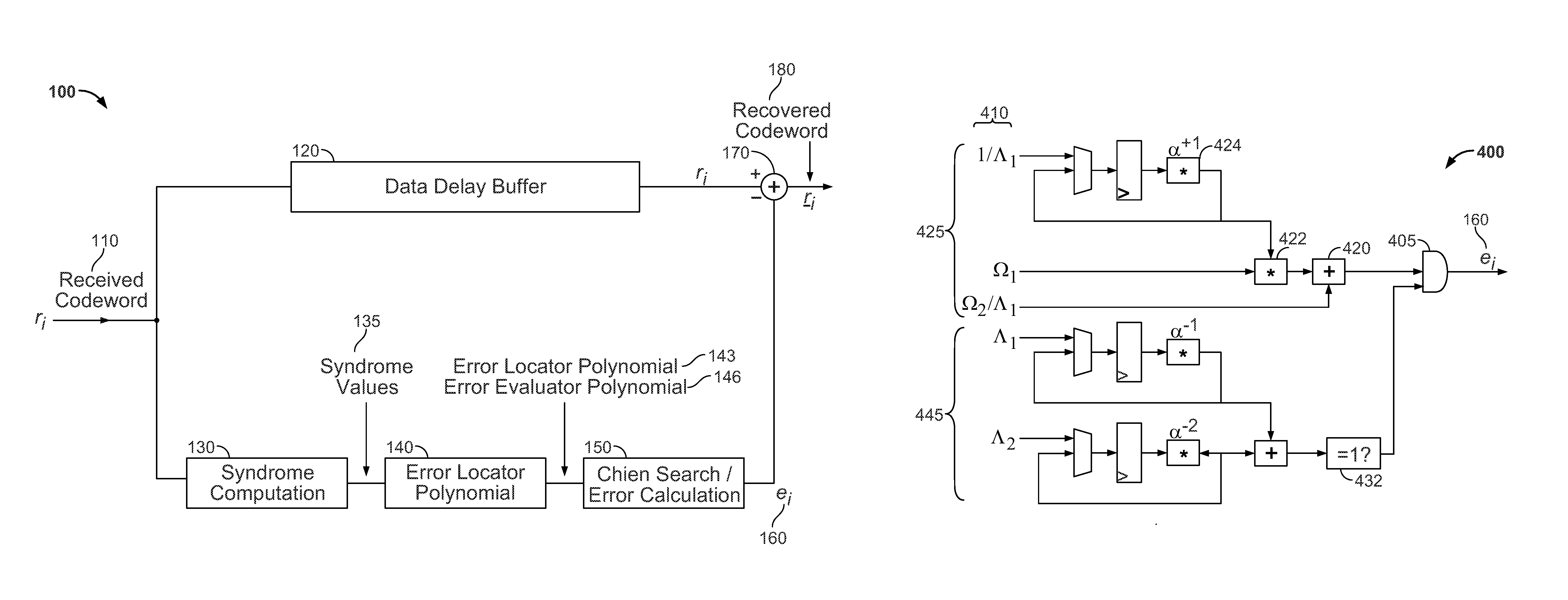
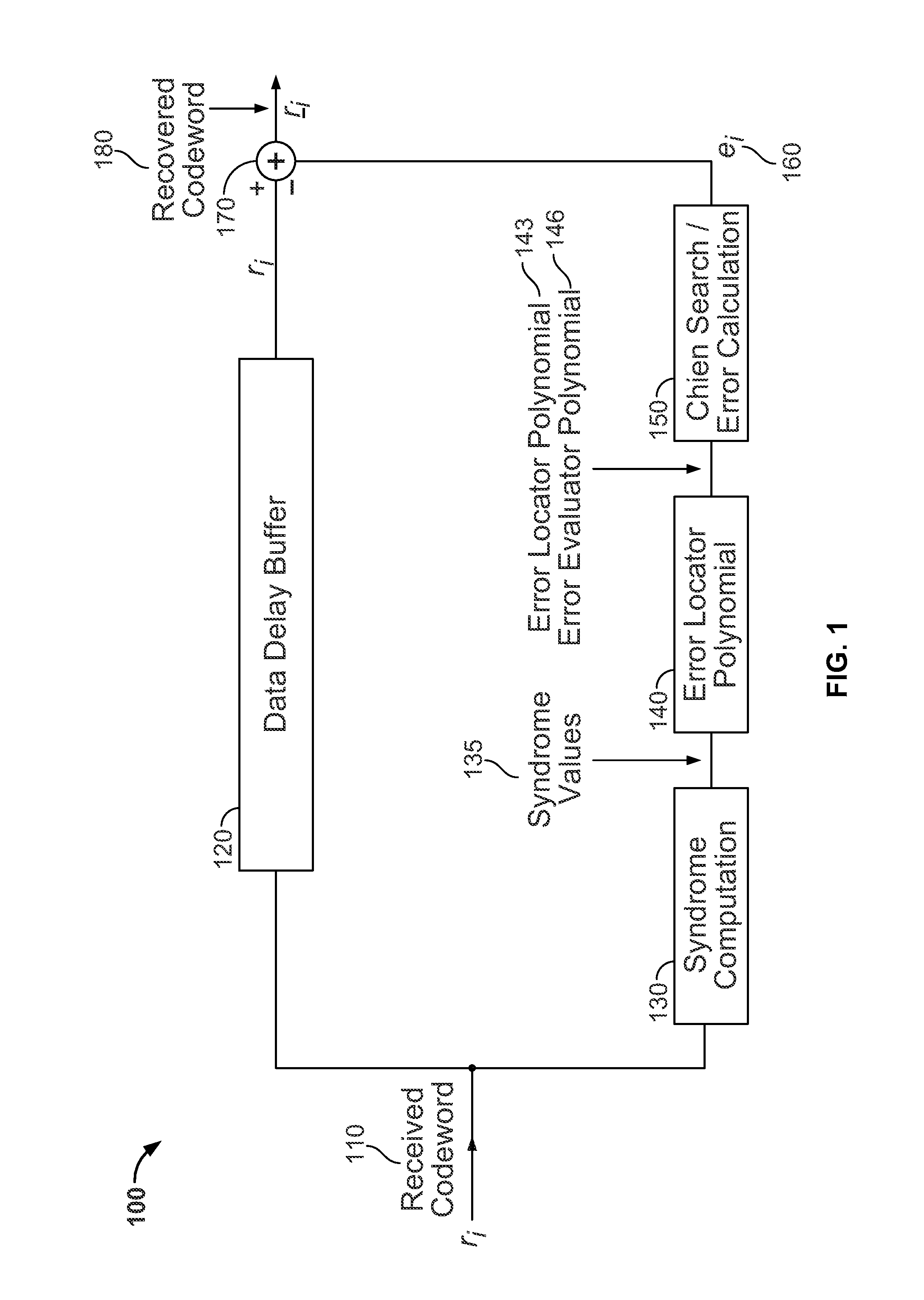
[0025]FIG. 1 illustrates a pipelined Reed-Solomon decoding architecture in accordance with an arrangement of the present invention. A decoder 100 is used to sequentially process received codewords to recover corresponding datawords. The decoder 100 receives the codewords through receiver circuitry (not illustrated in FIG. 1) over a ...


PUM


Abstract

In an arrangement of the disclosed systems, devices, and methods, a codeword encoded with a first number of check symbols is received and asymmetrically processed according to a second number of check symbols, where the second number of check symbols is less than the first number of check symbols, to produce an error locator polynomial and an error evaluator polynomial. A derivative of the error locator polynomial is produced by outputting a first polynomial term and a second polynomial term, wherein the second polynomial term is a constant. The derivative of the error locator polynomial is produced using a variable finite-field multiplier and without use of a divider.

Description

CROSS REFERENCE TO RELATED APPLICATION[0001]This application claims the benefit under 35 U.S.C. §119(e) of U.S. Provisional Application No. 61 / 563,989, filed Nov. 28, 2011, which is incorporated herein by reference in its entirety.BACKGROUND OF THE INVENTION[0002]Many modern applications encode data prior to transmission of the data on a network using cyclic error correcting codes such as Reed-Solomon codes. Such codes have the potential to provide powerful error correction capability. For example, a Reed-Solomon code of length n and including n−k check symbols may detect any combination of up to t=n−k erroneous symbols and correct any combination of up to └t / 2┘ symbols, where └•┘ denotes the floor function. However, decoder implementations for such codes are expensive in terms of an amount of required logic, e.g., in terms of a required number of adaptive look-up tables (ALUTs), and hence, in terms of a size, monetary cost, and power consumption. For example, a typical Reed-Solomon...

Claims


Application Information

Patent Timeline
IPC IPC(8): H03M13/00H03M13/03H03M13/15
CPCH03M13/1585H03M13/157H03M13/6502H03M13/1515H03M13/153H03M13/1545H03M13/1555
Inventor LANGHAMMER, MARTINRUMBOLT, CHUCK
Owner ALTERA CORP
Learn More