
Wireless communication of data symbols

a data symbol and wireless technology, applied in the field of wireless communication of data symbols, can solve the problems of high peak transmit power, achieve the effects of reducing transmit power, tightening replication pattern, and accurate selection of constellation points

Active Publication Date: 2013-01-08
GOOGLE TECHNOLOGY HOLDINGS LLC
View PDF13 Cites 54 Cited by
  • Summary
  • Abstract
  • Description
  • Claims
  • Application Information

AI Technical Summary

Benefits of technology

[0013]The invention may allow improved performance for a communication system wherein data symbols are communicated from a transmitter to a receiver. The invention may in particular provide improved MIMO performance with pre-equalization and reduced transmit powers. Furthermore, this may be achieved with a reduced error rate. A low complexity of both the transmitter and receiver operation can be achieved.
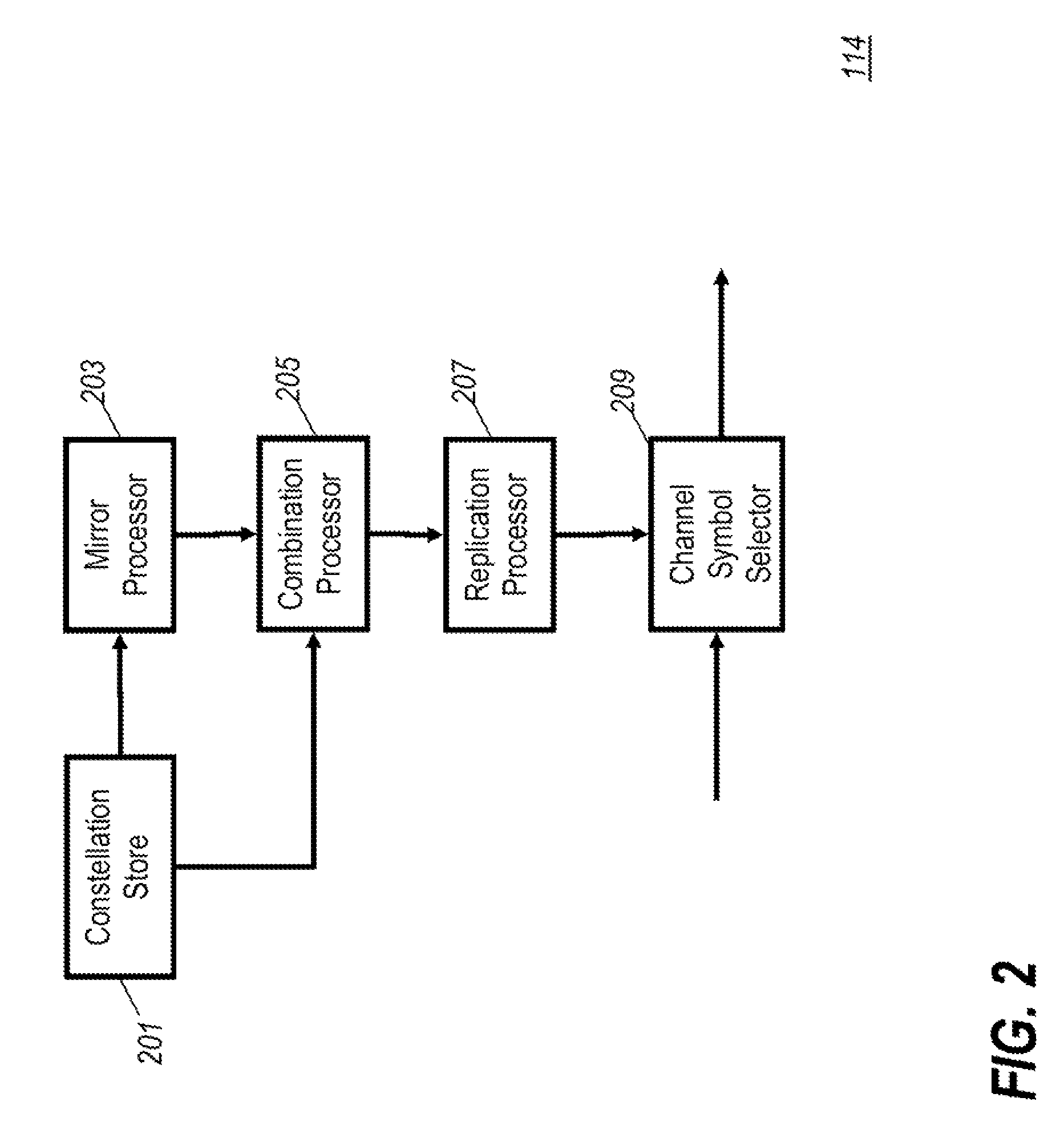
[0015]This may allow an improved trade-off between the transmit power and the error rate. In particular, corresponding constellation points may be moved closer together thereby providing a tighter replication pattern allowing a more accurate selection of constellation points that combine to result in a reduced transmit power. Furthermore, as this closer replication pattern reduces the distance between corresponding constellation points the minimum distance between non-corresponding constellation points still corresponds to the minimum distance within the first constellation thereby resulting in the error rate still being dominated by this minimum distance. Thus, the approach may allow a significant reduction in the transmit power while only introducing a negligent or acceptable error rate degradation.

Problems solved by technology

However, it tends to suffer from the limitation that it in principle requires unconstrained transmitted energy from the multiple antennas and thus in practice results in high peak transmit powers.

Method used


Image

  • Wireless communication of data symbols
  • Wireless communication of data symbols
  • Wireless communication of data symbols

Examples


Embodiment Construction

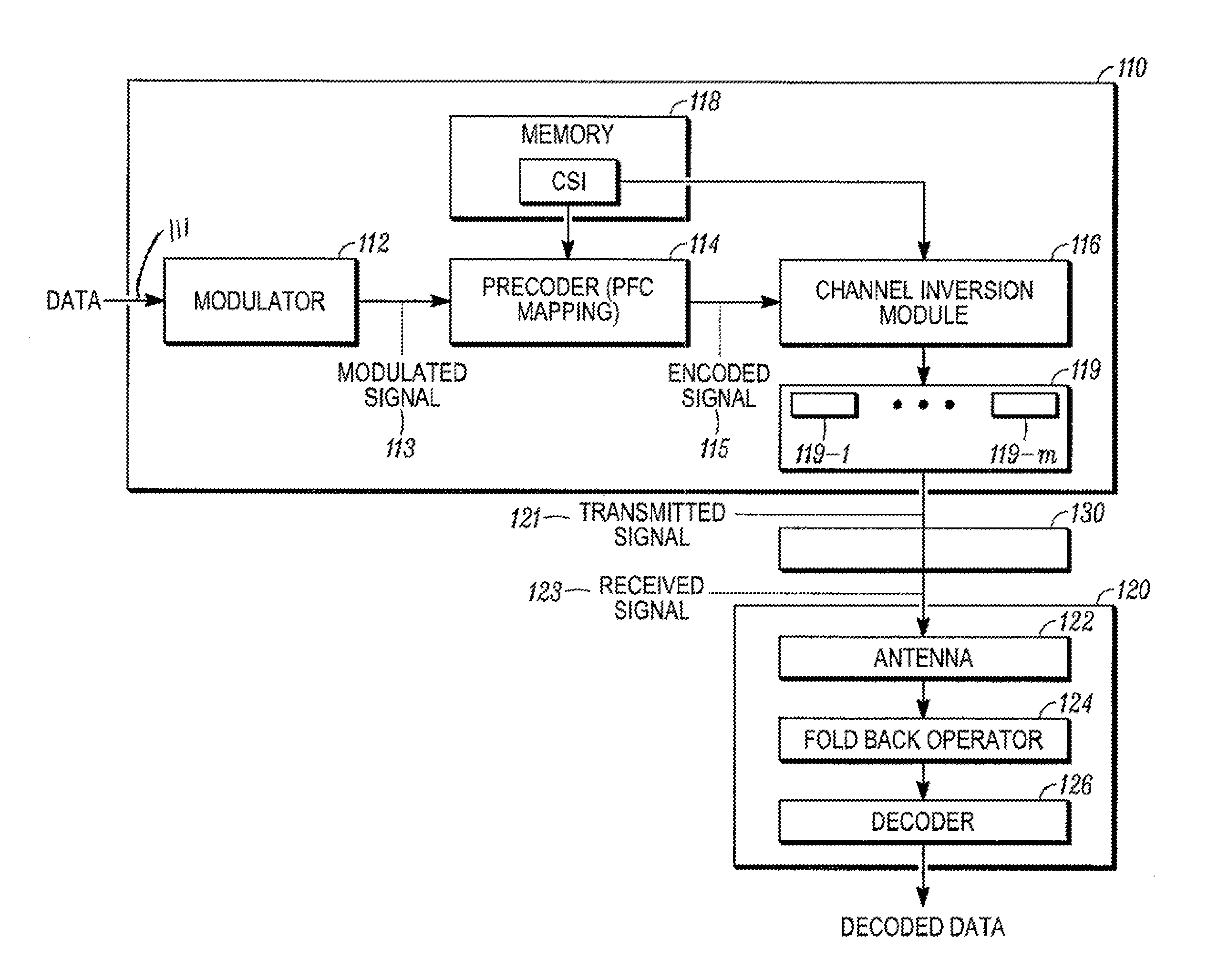
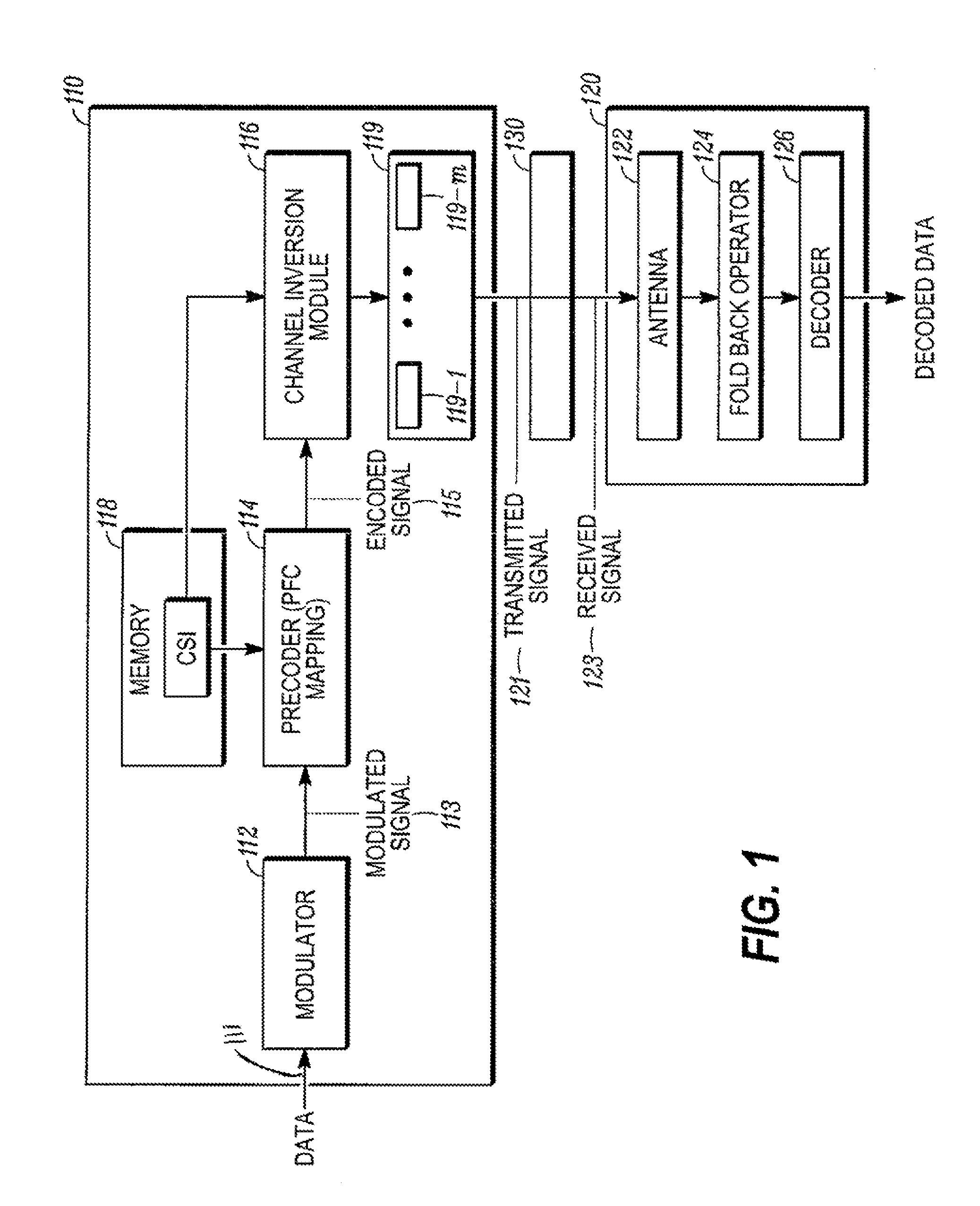
[0027]FIG. 1 illustrates an example of a block diagram of a multi-user MIMO communication system 100 in accordance with some embodiments of the present invention. The multi-user MIMO communication system 100 comprises a base station 110 (referred to herein as a transmitter 110) and a mobile station 120 (referred to herein as receiver 120) communicating via a communication link 130, e.g. an over an air interface. Even though only one receiver 120 is shown, any number of receivers may interface with the transmitter 110. Thus, the depiction of one receiver 120 is not meant to be a limitation. In any case, the multi-user MIMO communication system 100 enables the transmitter 110 to communicate with a receiver 120 or a number of receivers simultaneously.

[0028]The transmitter 110 of the multi-user MIMO communication system 100 comprises a modulator 112, a precoder 114, a channel inversion module 116, a memory 118, and multiple antennas 119-1 through 119-m. The modulator 112 modulates data ...


PUM


Abstract

A transmitter generates a constellation pattern comprising replications of a first constellation. Each replication has a replication offset relative to a neighbouring replication and alternates between corresponding to the first constellation and an axis mirrored constellation (mirrored around the real and / or imaginary axis). The transmitter selects from the pattern such that a symbol for a data value corresponding to a first constellation point of the first constellation is selected from all replications of this constellation point. The constellation point resulting in the lowest transmit power for a combination of a plurality of antennas may be selected. A receiver receives the selected symbol and provides a folding operation to compensate for replications and mirroring. The replication offset may be lower than the minimum distance between symbols in the first constellation thereby resulting in an improved trade off between transmit power and error probability, e.g. in a Multiple Input Multiple Output system.

Description

FIELD OF THE INVENTION[0001]The invention relates to wireless communication of data symbols and in particular, but not exclusively, to transmission of data symbols in a Multiple Input Multiple Output (MIMO) communication system.BACKGROUND OF THE INVENTION[0002]In recent years, the popularity of systems using wireless radio communication has increased substantially. For example, cellular communication systems and wireless networks have now become commonplace. The increased requirement for frequency spectrum resource has led to an increased desire for efficient communication and especially at higher frequencies and for higher data rates.[0003]For example, Broadband Wireless Access (BWA) systems are becoming common not only in fixed deployments but also in mobile deployments. In order to increase the capacity of such BWA systems, it is desirable to increase the data rate of the wireless communication. As a specific example, the Institute of Electrical and Electronic Engineers (IEEE) ha...

Claims


Application Information

Patent Timeline
Patent Type & Authority Patents(United States)
IPC IPC(8): H04L27/00
CPCH04L27/3416H04L27/3488
Inventor MAZET, LAURENT S.YANG, SHENG
Owner GOOGLE TECHNOLOGY HOLDINGS LLC
Learn More