Environment monitoring and recording tag with remote sensing capability

a technology of remote sensing and environmental monitoring, applied in the direction of electromagnetic radiation sensing, mechanical actuation of burglar alarms, instruments, etc., can solve the problems of significant degradation of the accuracy of the tag, limited onboard computational power of such devices, and large size of most such devices, so as to reduce the uncertainty of the package's subsequent environment history, reduce the uncertainty of battery discharge, and increase the accuracy of temperature monitoring.

Inactive Publication Date: 2015-05-19
ADVANCED ELECTRONICS TRACKING
View PDF73 Cites 18 Cited by
  • Summary
  • Abstract
  • Description
  • Claims
  • Application Information

AI Technical Summary

Benefits of technology

[0007]In one embodiment the accuracy of such low cost disposable tags can be improved by increasing the efficiency of the tag's limited onboard data processing ability.
[0008]In the proposed invention a temperature monitoring tag uses an on-board thermistor to generate resistance signals. The tag does not have its own temperature display so there is no requirement to convert the resistance values to temperature values. All on-board calculations are done on resistance units, leaving the tag free of temperature considerations. Hart-Steinhart conversions to the temperature domain are done only after the resistance data have been downloaded by RF or other means to a PC or other device with significantly greater computational ability, thus allowing more precise rounding when converting the data to estimated temperature values. This procedure results in improvement in accuracy by a factor of 10 to ±0.2° C. or better.
[0009]A similar increase in accuracy can be achieved for any environmental sensor including but not limited to vibration, pressure, radiation, shock, light, position and atmospheric pressure sensor monitoring where the generated signal is in the resistance domain. Leaving such data in the resistance domain to be converted to the domain of interest by a more powerful computing device only after the resistance data have been downloaded will increase the accuracy of measurement of the environmental variable of interest.
[0012]In another embodiment of the proposed invention it may be desirable to stop the tag's data acquisition process when the package reaches an interim or end destination. Reasons for doing this would include minimizing battery discharge and reducing uncertainty about the package's subsequent environment history.
[0020]In use the present invention would allow the tag to sense the package environment remotely via a sensor-containing probe being inserted into the interior of the package and the tag being attached to the exterior of the package. This confers major advances to prior art, such as sensing package temperatures below those at which electronics typically fail or become unreliable as for package contents cooled by dry carbon dioxide (“dry ice”) or other coolants (<−40° C.), sensing temperatures above those at which electronics typically fail or become unreliable (>100° C.) as for the contents of autoclaves, deep frying of foods (to 180° C.), steamer ovens (85 to 90° C. for extended periods), and related food processing applications, and placing the tag with its transmitting antenna on the outside of a package with only the probe penetrating the interior, reducing losses in the tag's RF signal due to passing through the package material. This increases the effective range of the tag's RF downloading ability and also makes possible the use of infrared (IR) as a data transmission medium.

Problems solved by technology

Most such devices are large, expensive and require the package to be opened to retrieve the environmental data from the device.
Due to size and cost considerations the onboard computational power of such devices is limited.
Due to the low computational power inherent in such low-cost tags, each conversion of a resistance value to a temperature value results in significant degradation of the tag's accuracy due to rounding errors.
This results in compounding the rounding errors as a function of the number of conversions.
Such devices are typically limited to accuracy of ±4° C.

Method used


Image

  • Environment monitoring and recording tag with remote sensing capability
  • Environment monitoring and recording tag with remote sensing capability
  • Environment monitoring and recording tag with remote sensing capability

Examples


Embodiment Construction

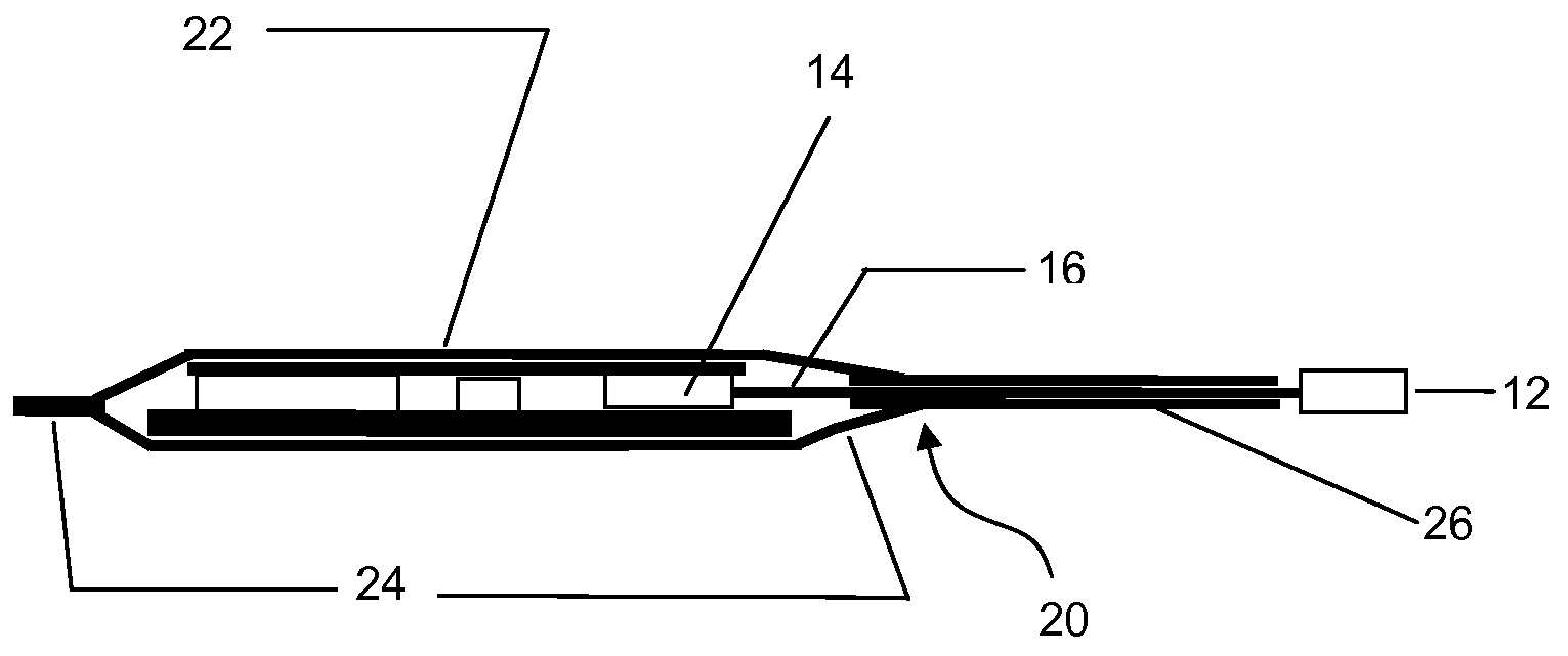
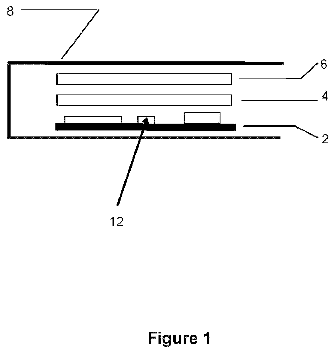
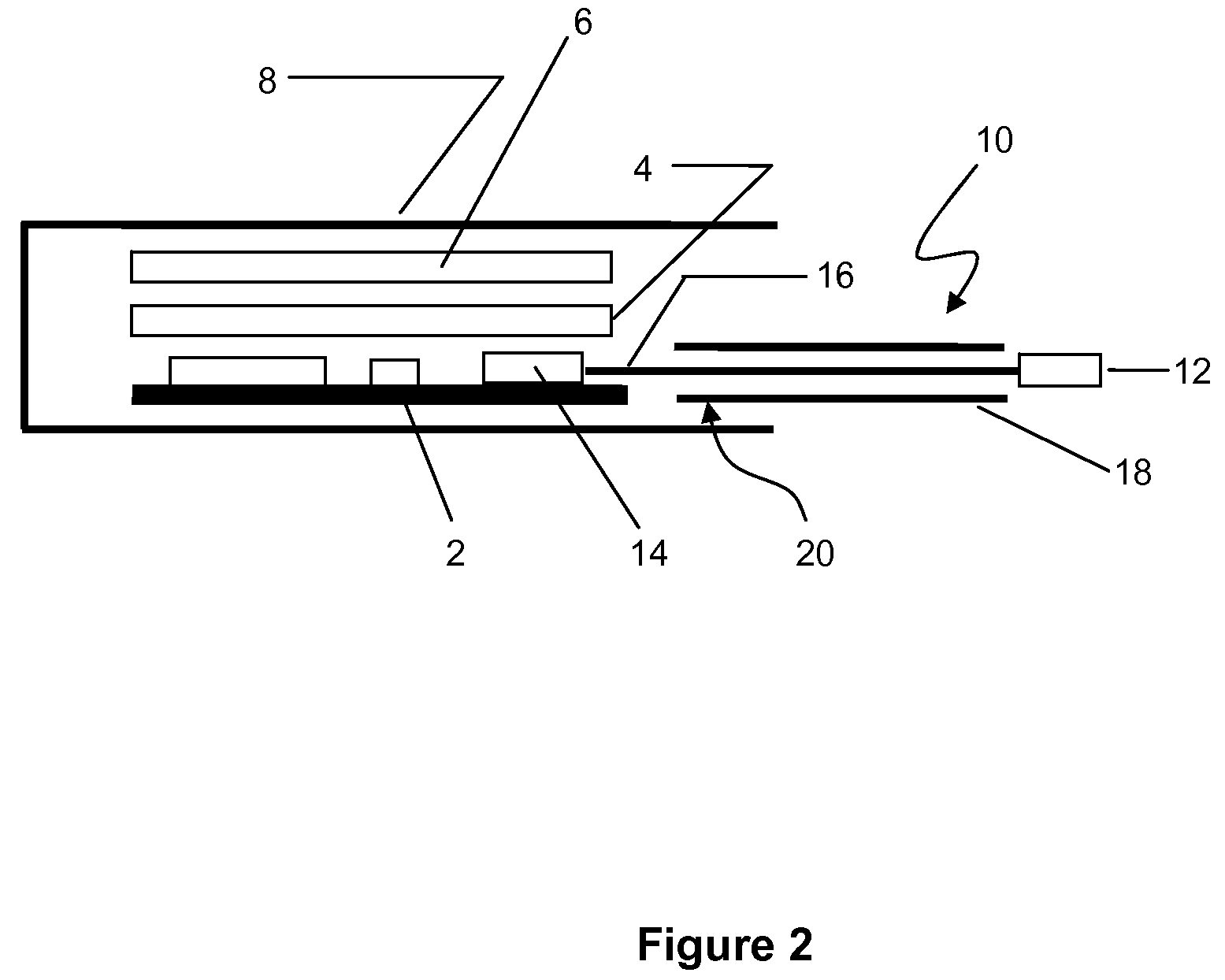
[0030]Referring to FIG. 1, an environment monitoring tag 2 comprising electronic components mounted on a substrate is covered by a layer of protective foam 4 over which is located an ESD layer 6 to reduce static buildup. The sandwich comprising tag 2, foam 4 and ESD layer 6 is inserted in a suitably-sized pouch or envelope 8 of food or pharmaceutical grade heat sealable flexible plastic. In one of its embodiments heat and pressure are applied to the perimeter of the sandwich sealing the elements into a waterproof unit.

[0031]In parallel to the claims hereinafter, the tag 2 includes an integrated circuit thereon, including memory, an antenna device for RF transmission of data acquired by the integrated circuit, a sensor 12 sensing environmental conditions to which the sensor 12 is subjected. The sensor 12 provides signals based on the environmental conditions to the integrated circuit. Sensor thermistor device 12 is provided for increasing the accuracy of the tag wherein the thermisto...


PUM


Abstract

A tag includes an integrated circuit thereon, including memory, antenna means for RF transmission of data acquired by the integrated circuit, a sensor sensing environmental conditions to which the sensor is subjected, the sensor providing signals based on the environmental conditions to the integrated circuit, a thermistor device of increasing the accuracy of the tag by confining on-board calculation data to a resistance domain and leaving conversion of the data to a temperature domain for an external device once the data is retrieved from the tag's memory.

Description

CROSS-REFERENCE TO RELATED APPLICATIONS[0001]This application claims the benefit, under 35 U.S.C. 119(a), of Canadian Application No. 2,627,258 filed on Mar. 27, 2008, which is hereby incorporated by reference.TECHNICAL FIELD[0002]The present device relates to a reusable environment monitoring tag that can be attached to the exterior of or placed within a product, package, article or container to sense the internal environment of the package including but not limited to temperature, vibration, pressure, radiation, shock, light, position and atmosphere.BACKGROUND[0003]Devices to monitor temperature and other environmental variables affecting packaged goods during shipping or through the logistics chain are in widespread use. Most such devices are large, expensive and require the package to be opened to retrieve the environmental data from the device. Petersen and Wilson in Canadian Patent No. 2627258 have described a small low cost, disposable device (tag) for monitoring, recording a...

Claims


Application Information

Patent Timeline
Patent Type & Authority Patents(United States)
IPC IPC(8): G08B13/14G01D9/00G01D21/00G06K19/07
CPCG01D21/00G01D9/005G06K19/0717G01D9/007
Inventor PETERSEN, MICHAELWILSON, ALANBROTZEL, DEAN
Owner ADVANCED ELECTRONICS TRACKING
Why Eureka
Try Eureka