Optical device having windage measurement instruments

a technology of optical devices and wind gauges, applied in instruments, analogue processes for specific applications, electric/magnetic computing, etc., can solve the problems of single riflemen not being able to use wind gauges and maintain a view of targets, and achieve the effect of reducing nois

Inactive Publication Date: 2015-05-26
BURRIS
View PDF105 Cites 32 Cited by
  • Summary
  • Abstract
  • Description
  • Claims
  • Application Information

AI Technical Summary

Benefits of technology

[0002]Various scope sighting systems (also referred to as optical devices or sights), for rifles, pistols, or other firearms are known in the art. In general, these include a plano containing a reticle located between an objective lens and an ocular lens. Additionally, an erector lens assembly is located between the objective and ocular lenses. The erector lens assembly may be movable to allow adjustable sighting of targets are various magnifications. The erector lens assembly allows targets a considerable distance from the rifleman to be viewed more easily through the scope, resulting in more accurate shots. Although the technology of riflescopes has improved over the years, a number of shortcomings are still present with even the most advanced riflescopes.

Problems solved by technology

Typically, a single rifleman cannot use a wind gauge and maintain a view of a target.

Method used


Image

  • Optical device having windage measurement instruments
  • Optical device having windage measurement instruments
  • Optical device having windage measurement instruments

Examples


Embodiment Construction

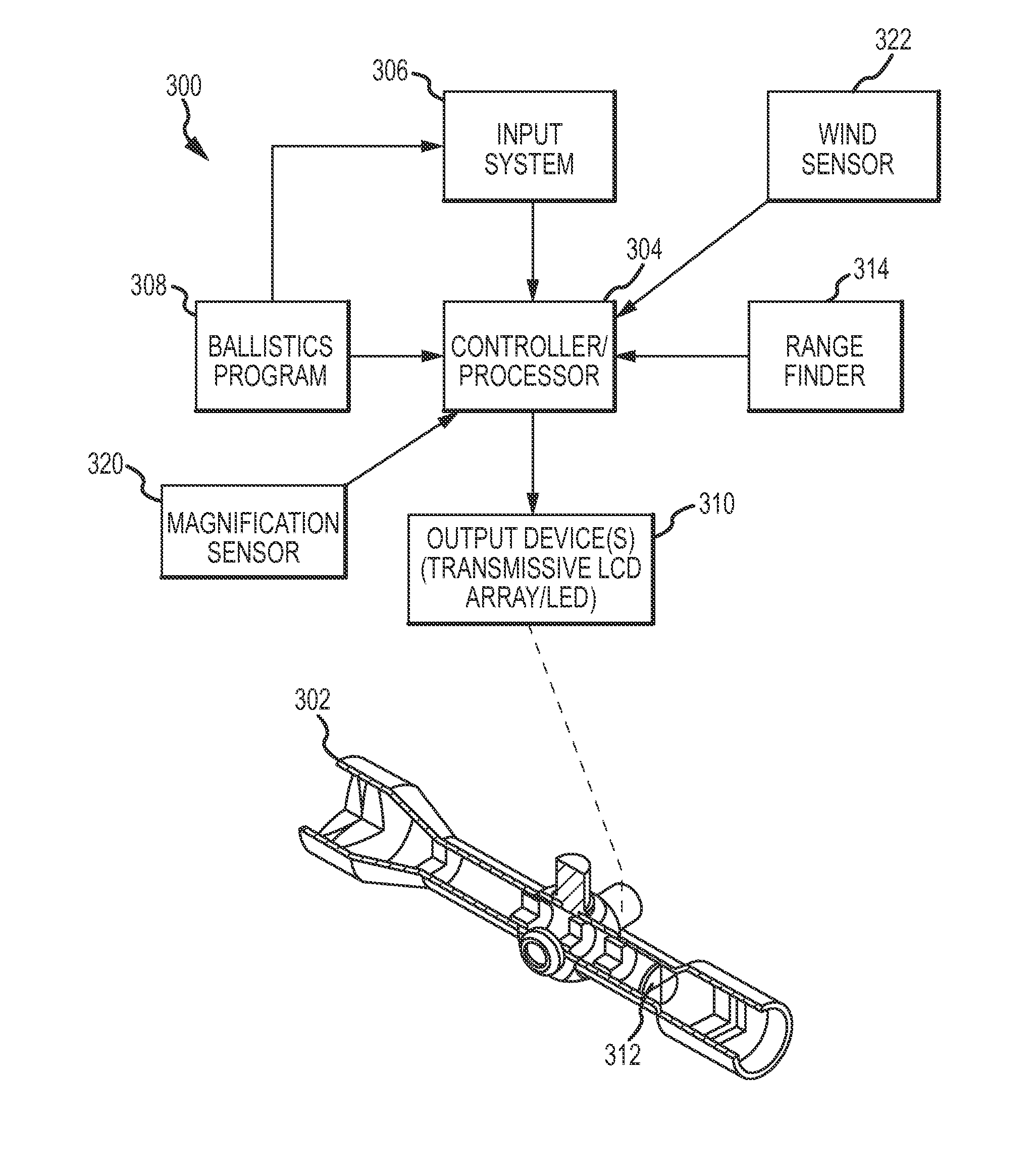
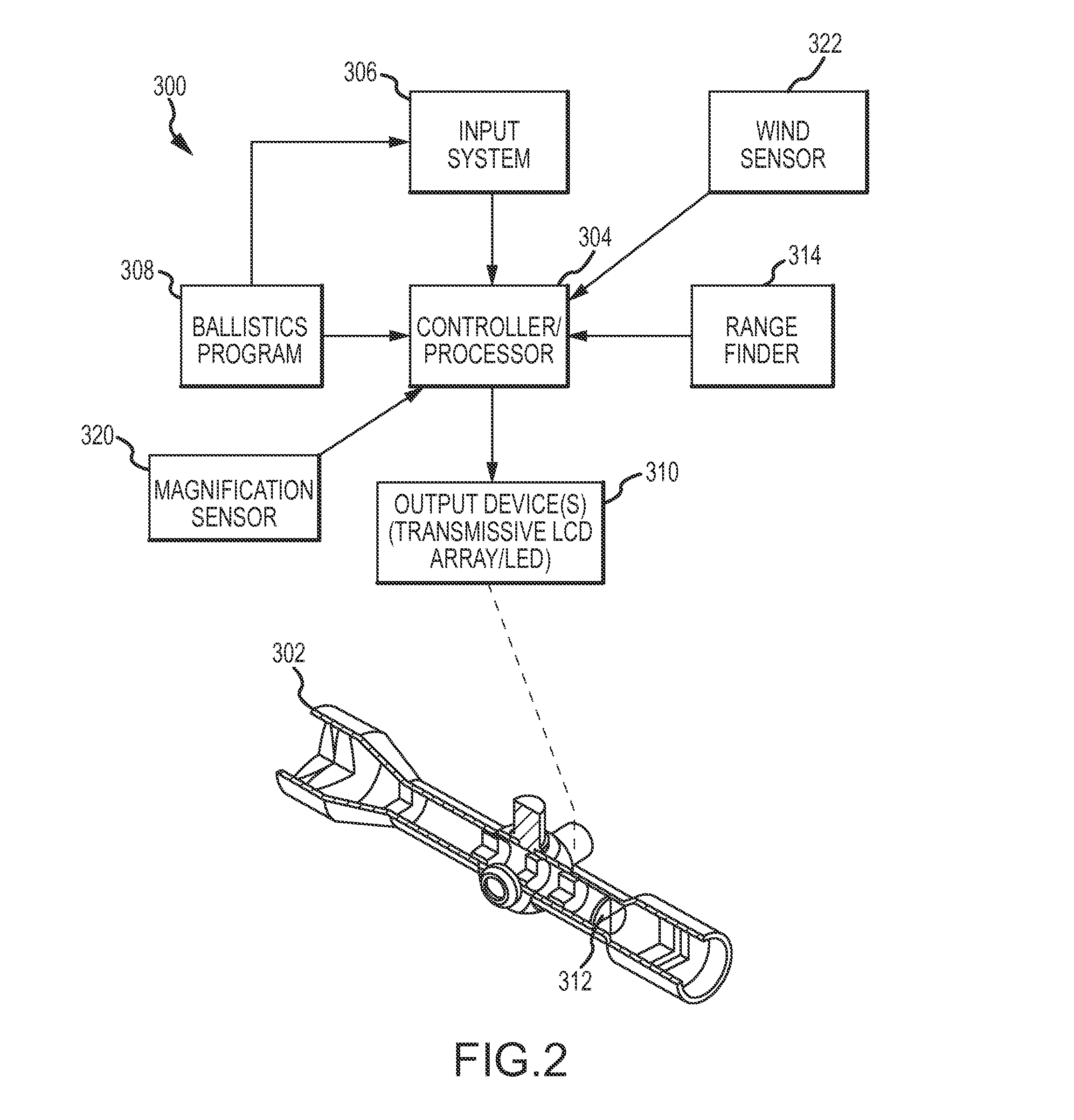
[0015]The present technology relates to new and improved embodiments of known sighting systems and methods (such as those described in U.S. Pat. No. 7,703,679, the disclosure of which is hereby incorporated by reference herein in its entirety), for correctly aiming a firearm or other implement. In embodiments, the present sighting system includes a lens position sensor, which may also sense the position of a cam tube or power ring, a processor (CPU), and an aiming point that can be manipulated by the CPU either mechanically or electrically. Other embodiments may include an optic device, a range input, a controller / processor, an input system, a ballistics program, and an aiming element display device. The optic device is any device that can visually acquire a target, such as an optical scope (e.g., for a rifle, handgun, etc.), or a camera with a viewfinder. The range input may be input from a range finder that may be any device that can determine the distance between the sighting sys...


PUM


Abstract

An optical device includes a housing containing a plurality of lenses. At least one of those lenses includes a reticle. An optical device and a processor are also located in the housing. A wind speed sensor is mounted to the housing and configured to send a wind speed signal corresponding to a wind speed to the processor. The processor calculates a wind speed based at least in part on the wind speed signal, and wherein the processor sends an output signal corresponding to the calculated wind speed to the output device.

Description

CROSS-REFERENCE TO RELATED APPLICATIONS[0001]This application claims priority to and the benefit of U.S. Provisional Patent Application Ser. No. 61 / 599,203, filed Feb. 15, 2012, entitled “Optical Device Having Windage Measurement Instruments,” the entire disclosure of which is hereby incorporated by reference herein in its entirety.INTRODUCTION[0002]Various scope sighting systems (also referred to as optical devices or sights), for rifles, pistols, or other firearms are known in the art. In general, these include a plano containing a reticle located between an objective lens and an ocular lens. Additionally, an erector lens assembly is located between the objective and ocular lenses. The erector lens assembly may be movable to allow adjustable sighting of targets are various magnifications. The erector lens assembly allows targets a considerable distance from the rifleman to be viewed more easily through the scope, resulting in more accurate shots. Although the technology of riflesc...

Claims


Application Information

Patent Timeline
Patent Type & Authority Patents(United States)
IPC IPC(8): G06G7/80F41G3/06F41G3/08
CPCF41G3/08F41G3/06
Inventor PATERSON, DOUGLAS F.BENNETTS, STEVEN A.
Owner BURRIS
Why Eureka
Try Eureka