Structure improvement of an orthopaedic implant of an artificial knee joint

a technology of knee joint and structure, applied in the field of structure improvement of an orthopaedic implant of a knee joint, can solve the problems of pain or inability to provide proper moving functions, dislocation between, and easy fracture, and achieve the effects of preventing deformation, stabilizing coupling, and enhancing practicability and inventiveness

Active Publication Date: 2015-06-02
UNITED ORTHOPEDIC CORP
View PDF3 Cites 0 Cited by
  • Summary
  • Abstract
  • Description
  • Claims
  • Application Information

AI Technical Summary

Benefits of technology

[0007]An objective of the present invention is to provide a structure improvement of an orthopaedic implant, which comprises a reinforcement inset in a tibial insert and coupled, in a downward direction, to a stem adaptor to drive a sleeve of the reinforcement to project beyond a bottom of the tibial insert for fitting into a groove defined in a tibial baseplate to provide the efficacies of stable coupling, resistance against external forces, the prevention of the deformation, and the extension of the lifespan thereby enhancing practicability and inventiveness of the present invention.
[0008]Another objective of the present invention is to provide a structure improvement of the orthopaedic implant, wherein a reinforcement is directly set inside an accommodating hole of a through region defined in a tibial insert and a sleeve of the reinforcement has a circumferential outer surface that forms threading or is made roughened, thereby providing the efficacies of increasing operation efficiency, providing safety of use, and making a stable coupling and thus enhancing the inventiveness and safety of the present invention.
[0009]A further objective of the present invention is to provide a structure improvement of the orthopaedic implant, wherein the components of the orthopaedic implant are of modular designs and suit for difference of individuals and allow for partial replacement to thereby offer the efficacies of being easy to use and reducing costs and thus enhancing the practicability and convenience of the present invention.
[0010]To achieve the above objectives, the present invention provides a structure improvement of the orthopaedic implant for connecting a distal femur and a proximal tibia, and a stem was implanted into proximal tibia, wherein an end of the stem formed a coupling hole with inner thread, in which formed to allow inter-engagement between the stem of the tibia and the structure improvement of the orthopaedic implant. The structure improvement of the orthopaedic implant comprises a tibial baseplate, a tibial insert, and a reinforcement. The tibial baseplate forms a recess having a bottom that has a central portion defining a through hole extending through the tibial baseplate, and an end of the stem is inserted in the through hole, and the through hole has a top circumference that defines a circumferential groove extending outward. The recess has a side wall defining a retention slot. The tibial insert includes a support and a projection, wherein an end of the tibial insert forming the projection corresponding to the recess of the tibial baseplate for press-fitting to the tibial baseplate. A retention pawl is formed on one side of the projection and is engageable with the retention slot of the tibial baseplate. A support is formed on the opposite end of the tibial insert and forms a through region that extends through the tibial insert, wherein the through region includes a bore and an accommodating hole, wherein the accommodating hole disposed close to the bore, and the diameter of the accommodating hole is greater than the diameter of the bore. The tibial insert forms two curved surfaces on opposite sides of the support to support contact and rolling. The reinforcement is fit in the accommodating hole and comprises a sleeve and a bolt, wherein an end of the sleeve forms a first opening, and the opposite end of the sleeve forms a stop with a second opening, wherein the first opening communicates with the second opening, and the bolt is movable received in the sleeve, wherein the bolt comprises a bolt head and a bolt body, and the diameter of the bolt head is greater than the diameter of the second opening and the diameter of the bore, and the diameter of the bolt body is smaller than the diameter of the second opening, and the bolt body is threading engagement with the inner thread of the coupling hole of the stem to drive the sleeve of the reinforcement to project beyond an end of the tibial insert for fitting into the groove of the tibial baseplate. As such, the advantages of stable coupling, resistance against stress, the prevention of the deformation, the extension of the lifespan, increasing safety of use are provided so as to realize practicability, inventiveness, safety, and convenience.

Problems solved by technology

Due to aging, joints of human beings may suffer wear or degradation caused by long term use or degeneration, leading to pain or incapability of providing proper moving functions, as a consequence of which daily living is affected.
Therefore, how to secure locking strength between the tibial insert and the tibial baseplate was one of most important issue to achieve successful TKR.
The tibial insert forms thereon a support that constrains the movement between the femoral implant and the tibial insert, but it is often made of plastics and is susceptible to fracture caused by long resistance against external forces acting thereon.
Daily activity of human beings causes loads and shear forces acting on the artificial knee joint, especially the tibial insert post and this may cause dislocation between the tibial insert and the tibial baseplate, or may even separate the tibial insert from the tibial baseplate.
However, this arrangement only improves the stability between the tibial insert and the femural implant.
This only improves the coupling between the two components, but does not increase the capability of resisting shear force.
This lowers the efficiency of operation.

Method used


Image

  • Structure improvement of an orthopaedic implant of an artificial knee joint
  • Structure improvement of an orthopaedic implant of an artificial knee joint
  • Structure improvement of an orthopaedic implant of an artificial knee joint

Examples


Embodiment Construction

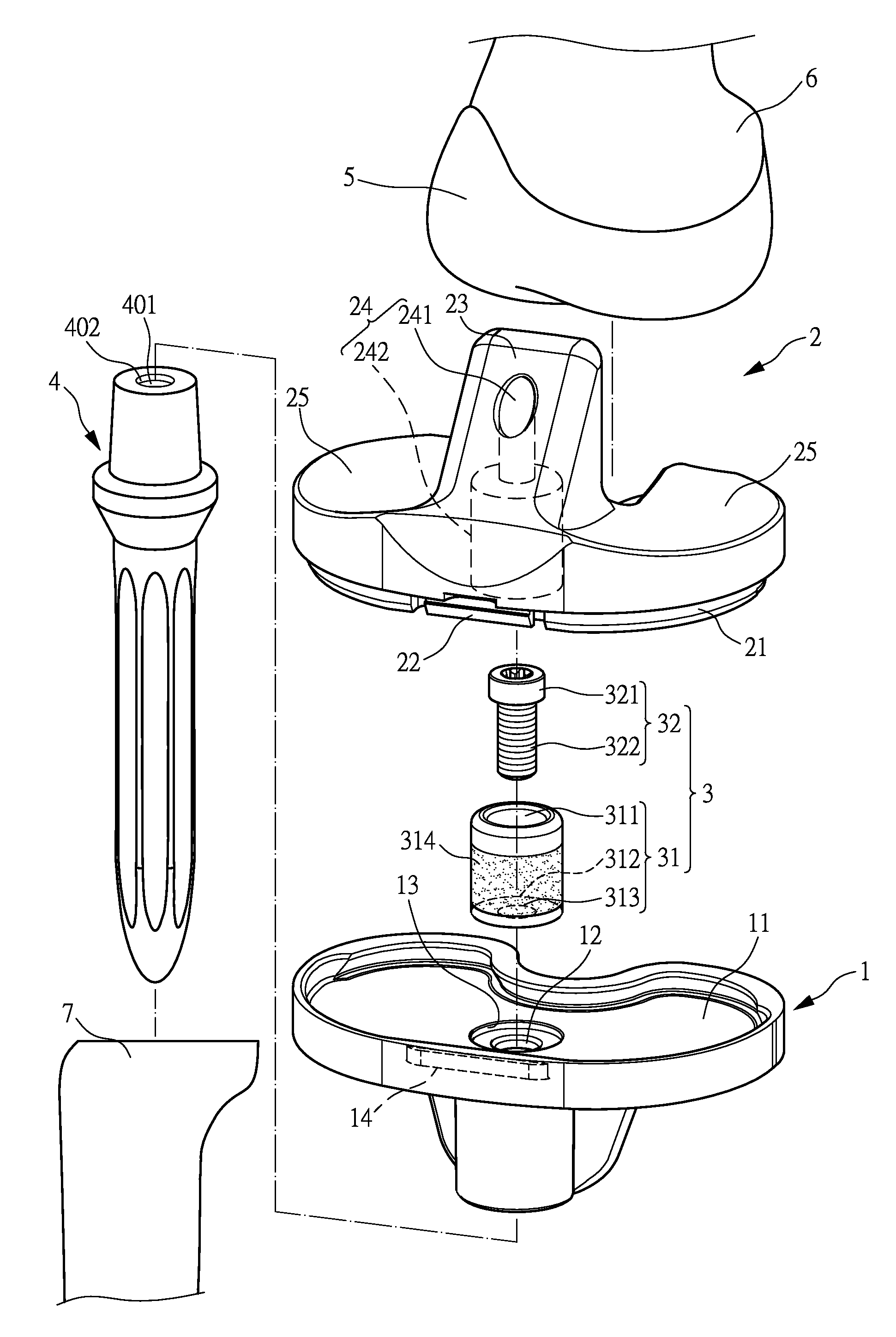
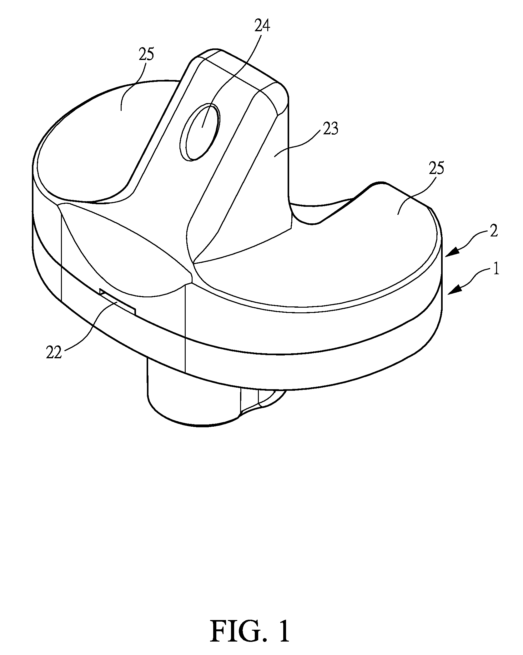
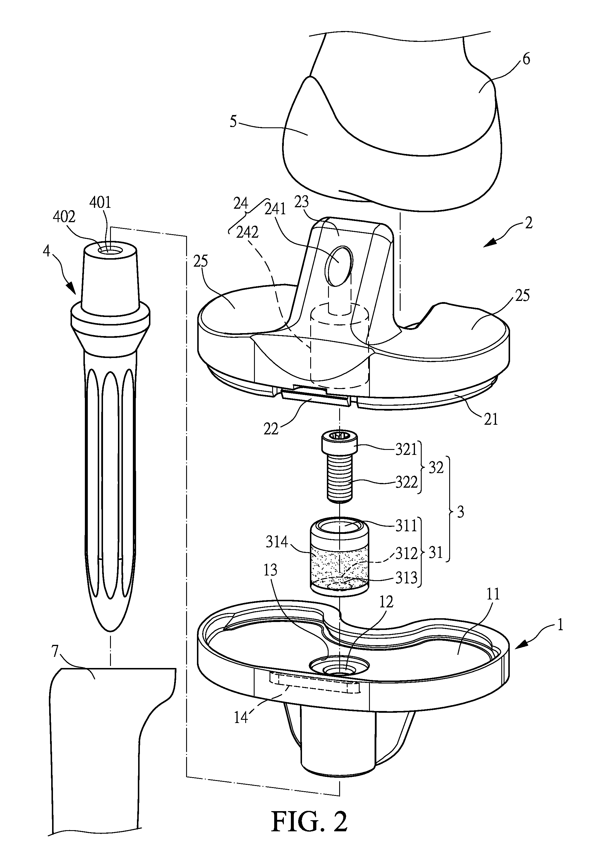
[0019]With reference to the drawings and in particular to FIGS. 1-3, which show, respectively, a perspective view, an exploded view, and a cross-sectional view of an orthopaedic implant constructed in accordance with the present invention, the orthopaedic implant of the present invention connected a femur 6 and a tibia 7, and a stem 4 was implanted into the tibia 7, wherein an end of the stem 4 formed a coupling hole 401 with inner thread 402, in which formed to allow inter-engagement between the stem 4 of the tibia 7. The orthopaedic implant of the present invention comprises a tibial baseplate 1, a tibial insert 2, and a reinforcement 3. The orthopaedic implant of the present invention comprises a tibial baseplate 1, a tibial insert 2, and a reinforcement 3.

[0020]The tibial baseplate 1 is of a modular design having various sizes and forms a recess 11. The recess 11 has a bottom that has a central portion defining a through hole 12 extending through the tibial baseplate, and an end...


PUM


Abstract

A structure improvement of orthopaedic implant for connecting a distal femur and a proximal tibia, and a stem was implanted into the proximal tibia, in which formed to allow inter-engagement between the stem of the tibia and the structure improvement of orthopaedic implant. The structure improvement of orthopaedic implant includes a tibial baseplate, a tibial insert, and a reinforcement. The tibial baseplate forms a recess having a bottom that has a central portion defining a through hole extending through the tibial baseplate. The tibial insert includes a support, a through region, and a projection, wherein an end of the tibial insert forming the projection corresponding to the recess of the tibial baseplate for press-fitting to the tibial baseplate. The reinforcement is inset in the tibial insert and includes a sleeve and a bolt. As such, the advantages of stable coupling includes force resistance, avoids insert loosening then extends prosthetic longevity.

Description

FIELD OF THE INVENTION[0001]The present invention relates to a structure improvement of an orthopaedic implant of a knee joint, and in particular to an orthopaedic implant of an artificial knee comprising a special design of a reinforcement to enhance stable coupling between a poly tibial insert and a metal tibial baseplate to offer the advantages of the resistance against external forces, the prevention of the deformation, and the extension of the lifespan, and to be applicable to severe bone damage or revision knee surgery.BACKGROUND OF THE INVENTION[0002]Due to aging, joints of human beings may suffer wear or degradation caused by long term use or degeneration, leading to pain or incapability of providing proper moving functions, as a consequence of which daily living is affected. When a joint suffers severe pathological changes, artificial knee joint replacement provides a measure to release the pain and improve joint function. The artificial knee joint is often composed of comp...

Claims


Application Information

Patent Timeline
Patent Type & Authority Patents(United States)
IPC IPC(8): A61F2/38
CPCA61F2/3868A61F2/3886A61F2/389
Inventor LIU, YU-LIANGLU, CHENG-KUANGLIAU, JIANN-JONG
Owner UNITED ORTHOPEDIC CORP
Why Eureka
Try Eureka