
Systems and methods for providing a distributed virtual stimulation cathode for use with an implantable neurostimulation system

a virtual stimulation and neurostimulation technology, applied in the field of implantable neurostimulation systems, can solve the problems of requiring more complex programming by the user, affecting the effect of the user, and draining power, so as to achieve the effect of increasing the stimulation coverage, saving energy, and increasing the energy consumption/current drain

Active Publication Date: 2015-06-02
PACESETTER INC
View PDF42 Cites 97 Cited by
  • Summary
  • Abstract
  • Description
  • Claims
  • Application Information

AI Technical Summary

Benefits of technology

This method enables efficient multi-site neurostimulation with reduced energy consumption and simplified programming, achieving additional stimulation coverage without draining the implantable pulse generator battery, and can be applied to various types of leads, including percutaneous and paddle leads.

Problems solved by technology

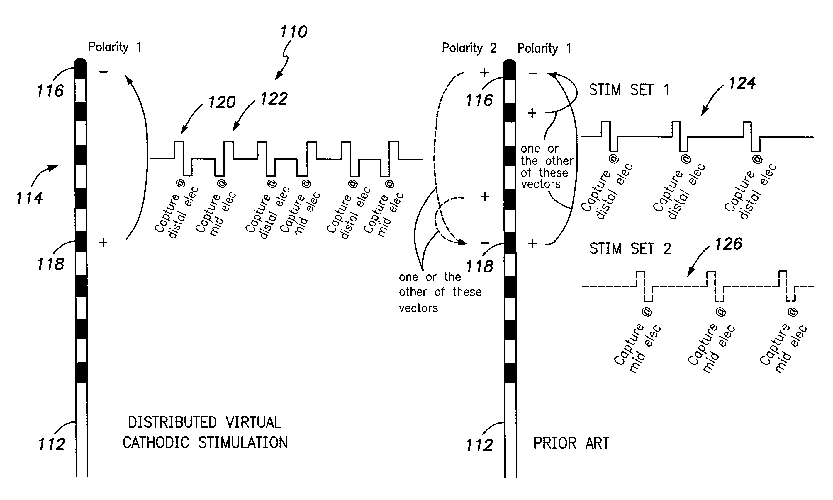
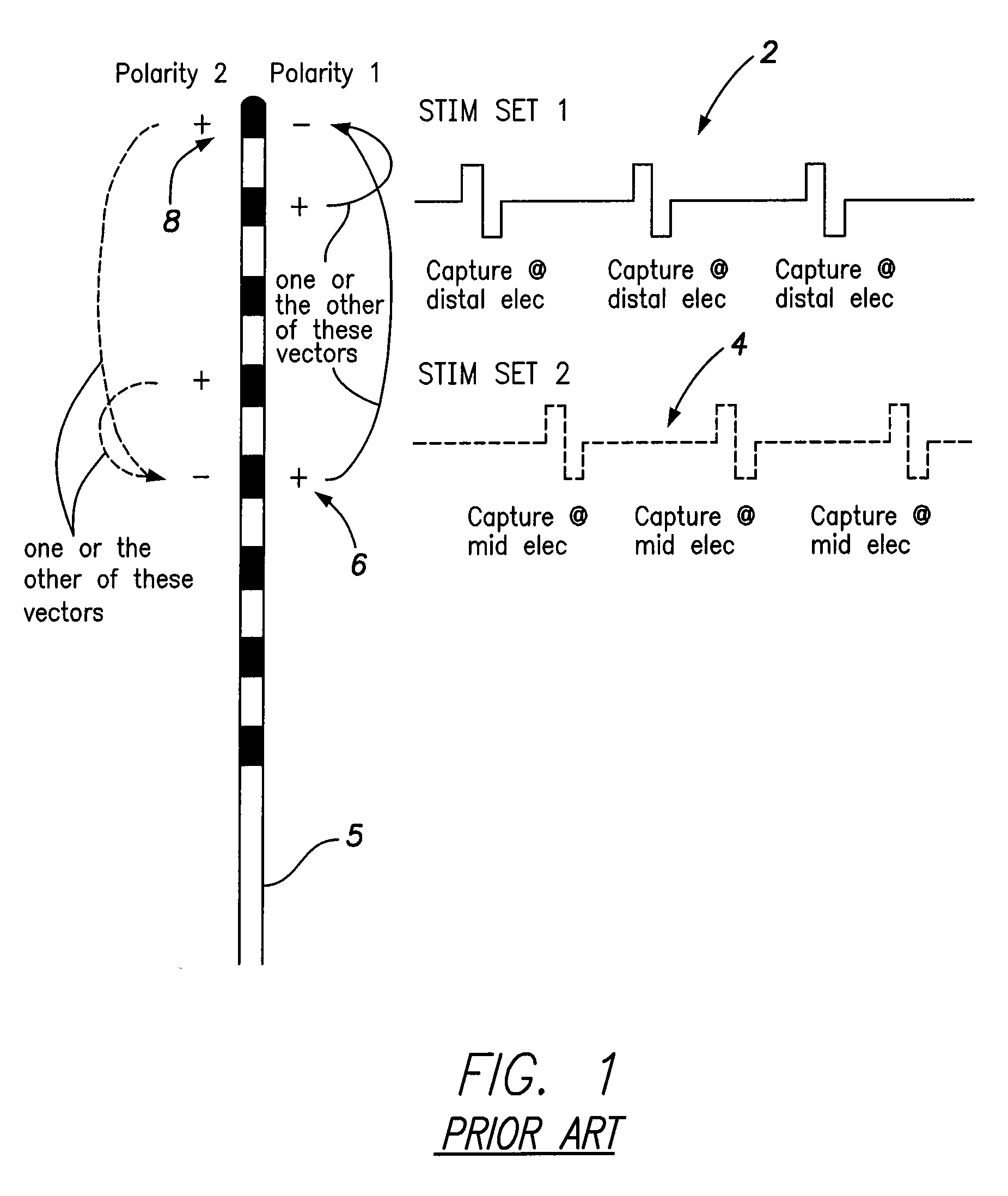
As such, to achieve anodal stimulation to deliver dual-site capture, much higher pulse amplitudes would be required, draining power and potentially causing unwanted accessory stimulation.
In addition to requiring more complex programming by the user (i.e. the clinician), multiple stimulation sets will tend to draw increased current from the implantable pulse generator (IPG) battery.
These issues may become even more problematic within neurostimulation systems used to treat cardiac disorders such as heart failure or arrhythmia (such as SCS to reduce heart rate or blood pressure, protect against ischemic signaling transduction outside of ischemic areas, modulate coronary circulation, modulate local and regional refractoriness, etc.) To achieve the needed stimulation at various locations along the cervical and thoracic spine to achieve these cardioprotective effects, still more complex SCS stimulation sets may be required, resulting in even greater current drain and programming complexity.

Method used


Image

  • Systems and methods for providing a distributed virtual stimulation cathode for use with an implantable neurostimulation system
  • Systems and methods for providing a distributed virtual stimulation cathode for use with an implantable neurostimulation system
  • Systems and methods for providing a distributed virtual stimulation cathode for use with an implantable neurostimulation system

Examples


Embodiment Construction

[0026]The following description includes the best mode presently contemplated for practicing the invention. This description is not to be taken in a limiting sense but is made merely to describe general principles of the invention. The scope of the invention should be ascertained with reference to the issued claims. In the description of the invention that follows, like numerals or reference designators are used to refer to like parts or elements throughout.

Overview of SCS System

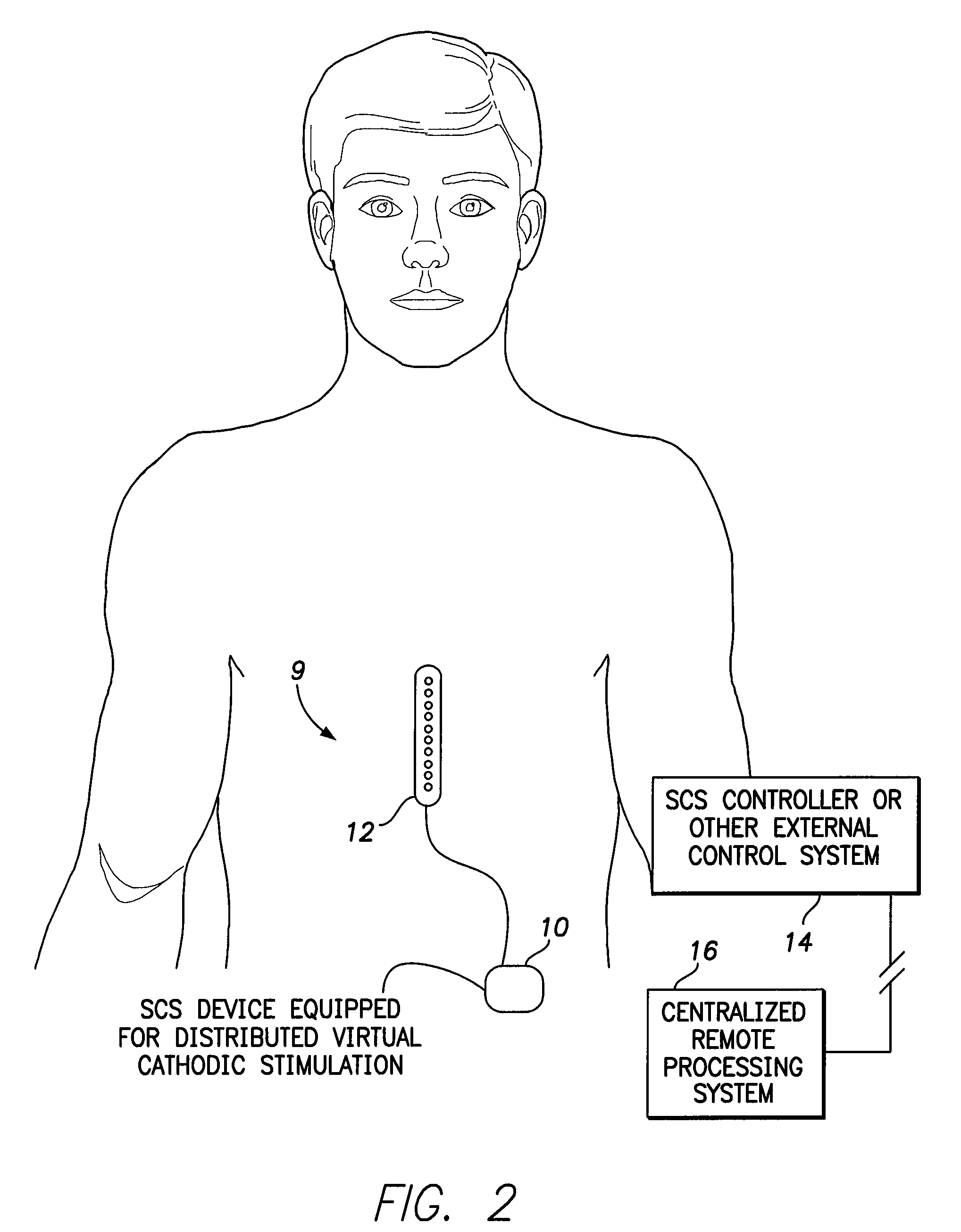
[0027]FIG. 2 illustrates an implantable medical system 9 having an SCS device 10 equipped for distributed virtual cathodic stimulation. The stimulation is delivered via an SCS lead or lead array 12 shown in FIG. 2 in stylized form. See FIGS. 7 and 8, discussed below, for illustrations of exemplary leads. The operation of SCS device 10 is controlled by an SCS controller 14 or other external system that programs the implanted device using one or more stimulation sets (Stim Sets) initially specified by a clinic...


PUM


Abstract

Techniques are provided for controlling and delivering spinal cord stimulation (SCS) or other forms of neurostimulation. In one example, neurostimulation pulses are generated wherein successive pulses alternate in polarity so that a pair of electrodes alternate as cathodes. Each pulse has a cathodic amplitude sufficient to achieve cathodic capture of tissues adjacent the particular electrode used as the cathode for the pulse. The neurostimulation pulses are delivered to patient tissues using the electrodes to alternatingly capture tissues adjacent opposing electrodes via cathodic capture to achieve a distributed virtual stimulation cathode. Various pulse energy savings techniques are also set forth that exploit the distributed virtual stimulation cathode.

Description

RELATED APPLICATIONS[0001]This application claims the benefit of U.S. Provisional Patent Application Ser. No. 61 / 793,688, filed Mar. 15, 2013, entitled “Systems and Methods for Providing a Distributed Virtual Stimulation Cathode for Use With an Implantable Neurostimulation System,” which is fully incorporated by reference herein.FIELD OF THE INVENTION[0002]The invention generally relates to implantable neurostimulation systems such as spinal cord stimulation (SCS) systems and, in particular, to techniques for controlling the stimulation generated by such systems.BACKGROUND OF THE INVENTION[0003]SCS is a type of neurostimulation primarily intended to manage chronic pain, particularly within the back, neck, arms or legs. Benefits of SCS or other forms of neurostimulation may include: a reduction in pain; a reduction or elimination of the use of pain medications; and increased activity levels and an improved overall quality of life. Neurostimulation has been used to manage pain from fa...

Claims


Application Information

Patent Timeline
Patent Type & Authority Patents(United States)
IPC IPC(8): A61N1/36A61N1/05
CPCA61N1/36071A61N1/0553
Inventor ROSENBERG, STUARTCHOLETTE, MARTINMIN, XIAOYI
Owner PACESETTER INC
Learn More