
Concrete distributing device and control method, control system and electrical control system for composite motion of boom thereof

a technology of concrete distributing device and control system, which is applied in the direction of process and machine control, transportation and packaging, instruments, etc., can solve the problems of severe increase in labor intensity, compromise of operating efficiency and movement stability of the boom,

Active Publication Date: 2015-06-02
ZOOMLION HEAVY IND CO LTD +1
View PDF11 Cites 3 Cited by
  • Summary
  • Abstract
  • Description
  • Claims
  • Application Information

AI Technical Summary

Benefits of technology

The solution ensures the boom moves along the intended motion track by reducing actuating mechanism speeds proportionally, independent of load differences, thereby enhancing operational efficiency and stability during composite motion.

Problems solved by technology

The drawback of load-sensitive hydraulic system will be exposed, i.e., the flow is taken to meet the demand of knuckle arms that bear lower loads, while the speeds of movement of knuckle arms that bear higher loads can't reach the values expected by the operator; as a result, the motion track of the boom end will deviate from that expected, and the operator has to change the openness of the operating handle continually to correct the motion track, and thereby the labor intensity is severely increased, and the operating efficiency and movement stability of the boom are compromised.

Method used

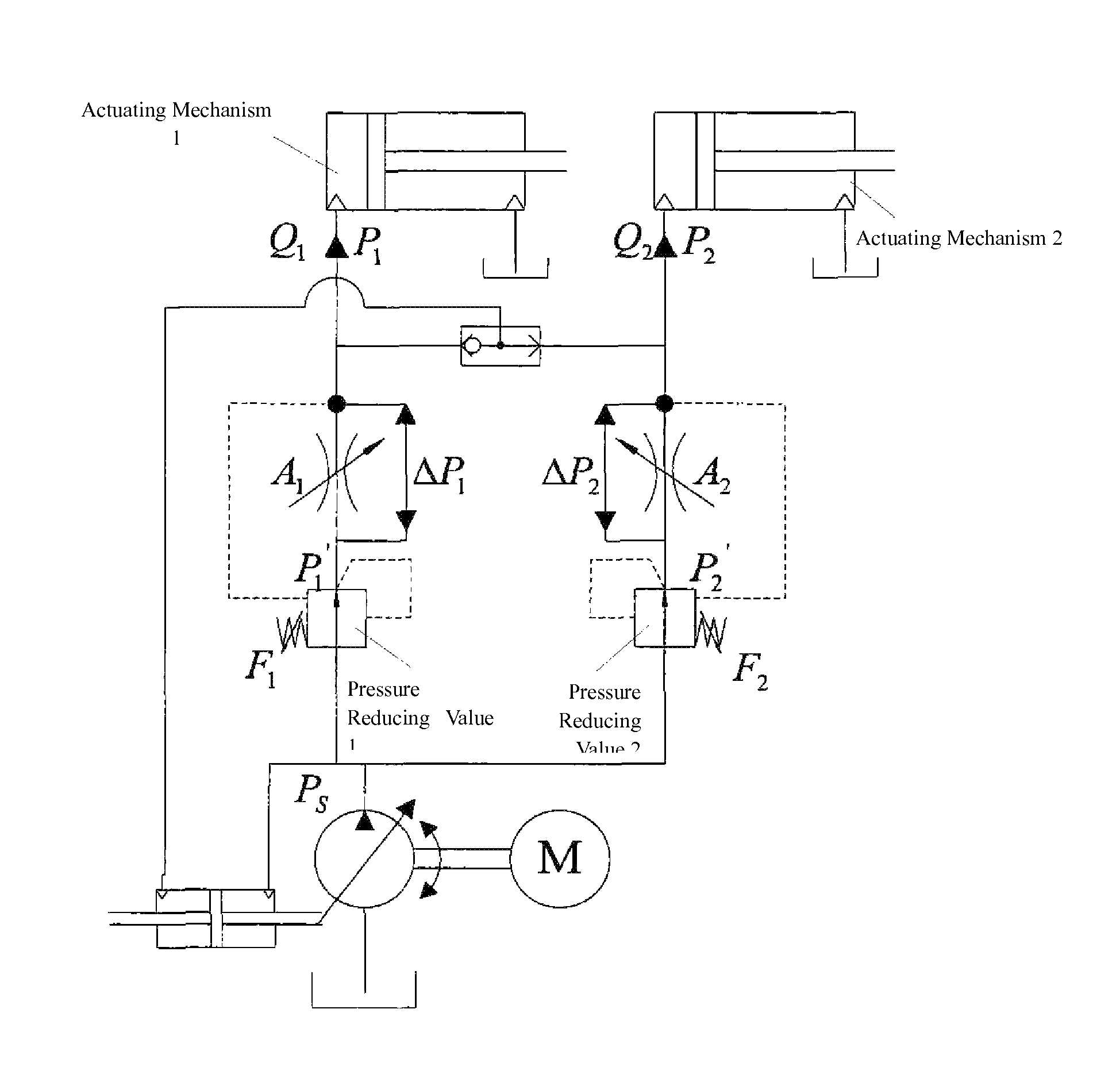
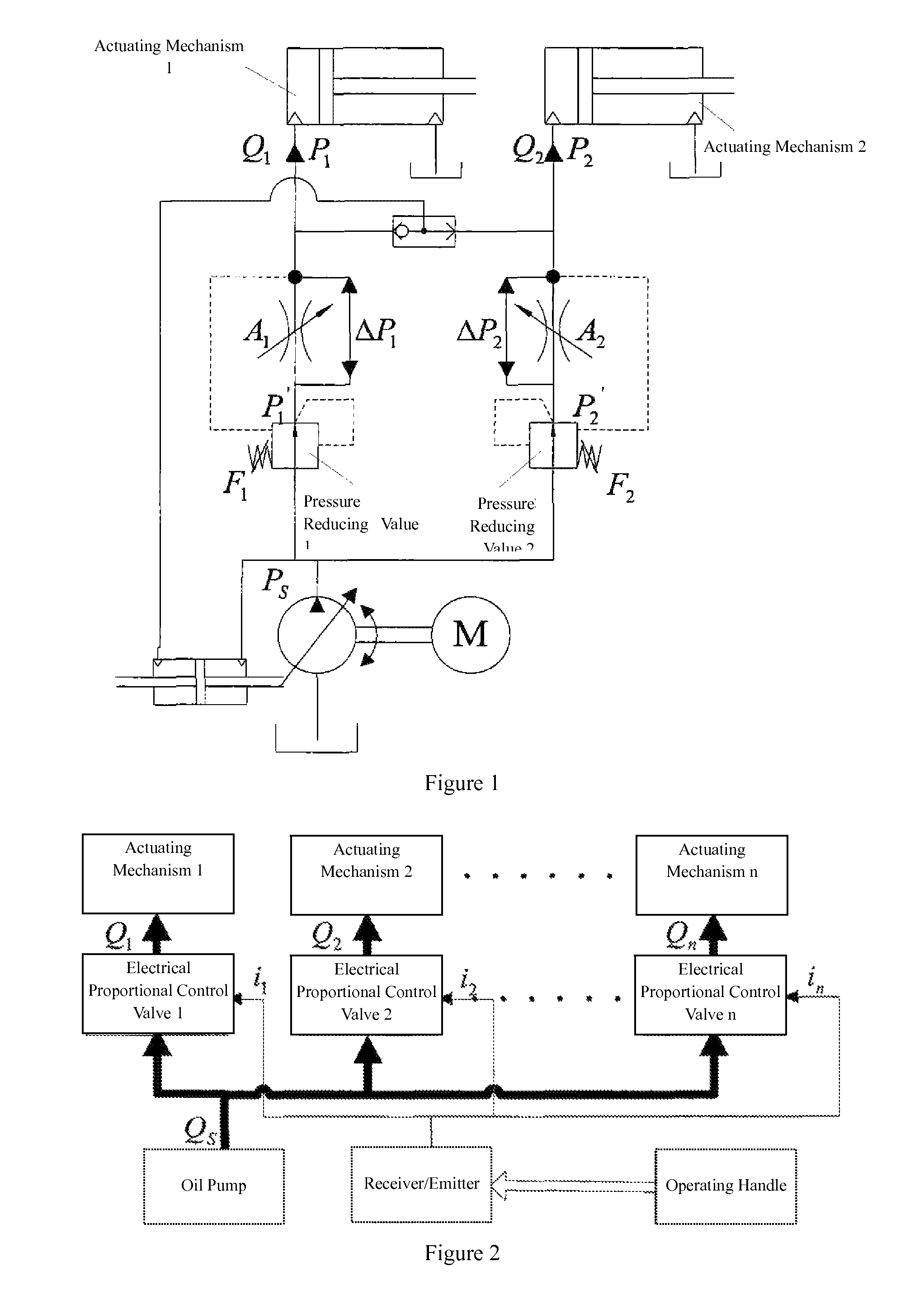

Image

  • Concrete distributing device and control method, control system and electrical control system for composite motion of boom thereof
  • Concrete distributing device and control method, control system and electrical control system for composite motion of boom thereof
  • Concrete distributing device and control method, control system and electrical control system for composite motion of boom thereof

Examples


Embodiment Construction

[0041]Hereunder embodiments of the present invention will be described with reference to the accompanying drawings. However, it should be appreciated that the present invention can be implemented in different ways confined and covered by the claims.

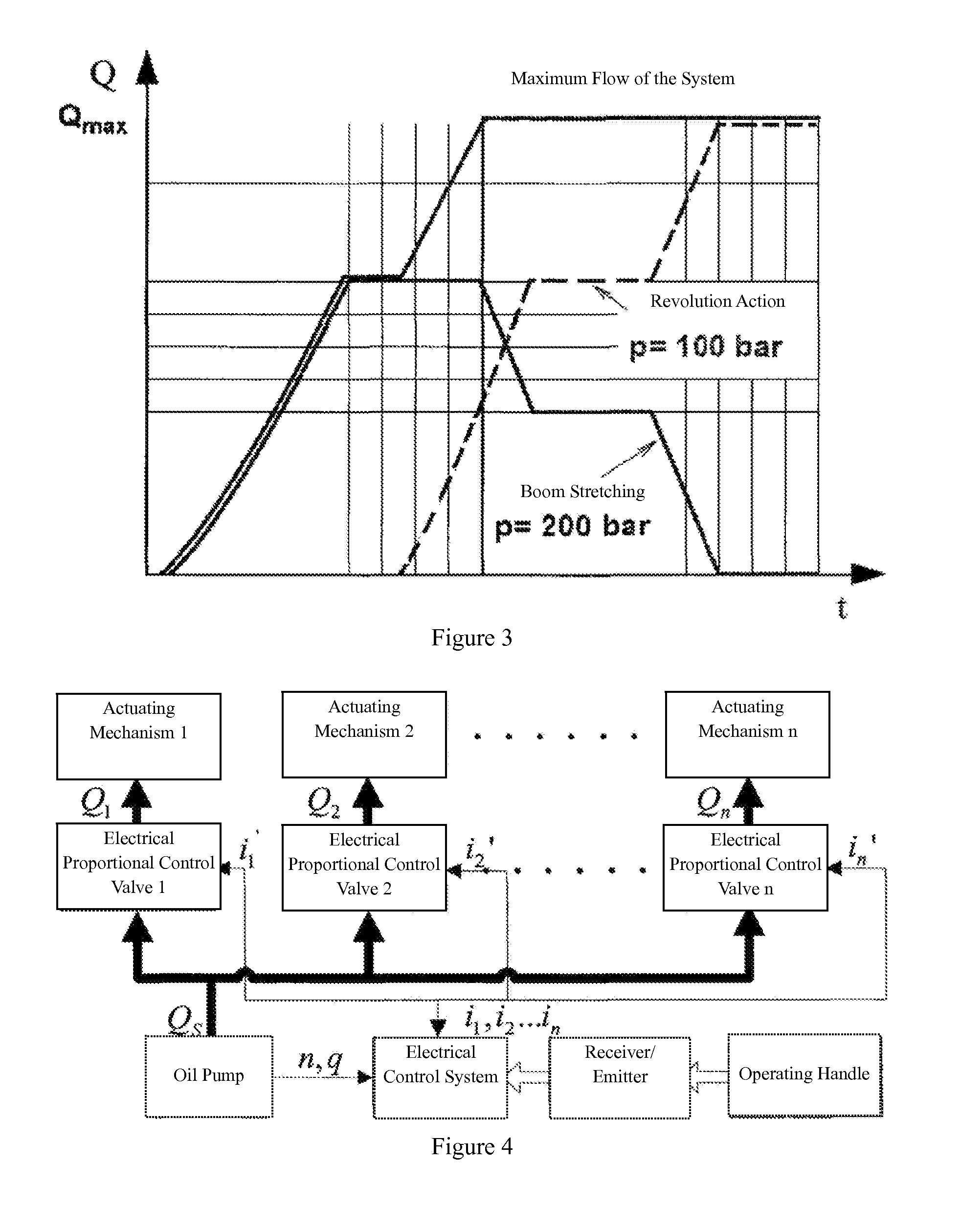
[0042]FIG. 4 is a schematic diagram of a control system for controlling the composite motion of a boom of concrete distributing device in the present invention. As shown in FIG. 4, the control system for a boom of concrete distributing device provided in the present invention comprises an electrical control system, which is connected via signals with an operating handle and is also connected via signals with a sensor that detects the rotation speed of a boom pump, and calculates the flow of the boom pump according to the displacement of the boom pump and the signals from the sensor.

[0043]A receiver / emitter for wireless or wired connection is arranged between the electrical control system and the operating handle. When the boom of concrete...


PUM


Abstract

Disclosed are a concrete distributing device and a control method, a control system and an electrical control system for composite motion of a boom thereof. The control method comprises the steps as follows: calculating the flow of a boom pump when an operating handle sends a command; according to the command sent by the operating handle, calculating theoretical demand flow of all actuating mechanisms of the boom and theoretical control signals of all electronic proportional control valves; comparing the total theoretical demand flow of the actuating mechanisms with the flow of the boom pump; providing the theoretical control signals to all the electronic proportional control valves when the flow of the boom pump is greater than or equal to the total theoretical demand flow of the actuating mechanisms, otherwise, providing actual control signals smaller than the theoretical control signals to all the electronic proportional control valves and reducing the movement speeds of all the actuating mechanisms proportionally. In this way, when undersaturation of system occurs to the composite motion of the boom, the movement speeds of all the actuating mechanisms are reduced proportionally independent of the load difference of the actuating mechanisms, thereby ensuring that the boom can move in a motion track expected by an operator.

Description

TECHNICAL FIELD[0001]The present invention relates to a concrete distributing device, a control system for controlling the composite motion of a boom of concrete distributing device, a control method for controlling the composite motion of a boom of concrete distributing device, and an electrical control system for controlling the composite motion of a boom of concrete distributing device.BACKGROUND OF THE INVENTION[0002]The boom of concrete distributing device usually comprises 3-6 knuckle arms, each of which is controlled by an actuating mechanism to stretch out or fold back.[0003]Presently, hydraulic systems for boom control of concrete distributing devices are usually single loop hydraulic systems that employ a single pump and a plurality of actuating mechanisms.[0004]To ensure the plurality of actuating mechanisms can act simultaneously and the movement speeds of the actuating mechanisms can be regulated steplessly independent of the load, the hydraulic system is usually a load...

Claims


Application Information

Patent Timeline
Patent Type & Authority Patents(United States)
IPC IPC(8): G05D7/00B66C13/06B66C13/20E04G21/04
CPCB66C13/066B66C13/20E04G21/0463E04G21/0418E02F9/2228E02F9/2232F15B2211/30535F15B2211/327F15B2211/351F15B2211/665F15B2211/6654F15B2211/71F15B2211/78G05B19/46
Inventor WAN, LIANGWANG, JIAQIANLI, PEILINWANG, SHUAI
Owner ZOOMLION HEAVY IND CO LTD
Learn More