Laser alignment device for use with a drill rig

a laser alignment and drill rig technology, applied in the field of laser alignment devices for use with drill rigs, can solve the problems of rejection of boreholes and difficulty in obtaining the level of accuracy that is demanded by geologists

Inactive Publication Date: 2015-06-02
PRECISION ALIGNMENT HLDG
View PDF19 Cites 2 Cited by
  • Summary
  • Abstract
  • Description
  • Claims
  • Application Information

AI Technical Summary

Benefits of technology

[0017]The present invention is directed to an adjustable hanging rack, which may at least partially overcome at least one of the abovementioned disadvantages or provide the consumer with a useful or commercial choice.
[0027]As discussed above, it is typically difficult to obtain the level of accuracy of alignment of the drill that is demanded by the geologists and surveyors using the known technique of string lines and measuring tapes. The present invention obviates the need for string lines and droppers and measuring tapes and increases the accuracy of the alignment of the drill rig and thereby the precision of the holes which is drilled.
[0031]Preferred methods of attachment include pin and slot or clamping arrangements but most preferred is a magnetic attachment. A magnetic attachment increase utility of the device as the device can be attached to any metal portion of the drill rig according to the preference the user.
[0044]A further option is to have an alarm (which could be a light) which lights up when the lasers are correctly aligned. To do so, a reflective strip may be placed on the survey marker and if the laser beam is correctly aligned, the laser beam will bounce off the reflective strip and back to a sensor provided on the laser unit which would then activate the alarm when the laser is correctly aligned. An audio alarm may be provided although a mine is a very noisy environment and a visual alarm is probably of most benefit. A further option is to have a digital inclinometer attached to the laser unit (typically to the telescopic rod). This can then allow the correct elevation or inclination of the drill rig to be quickly determined, and together with the two lasers (to determine the azimuth), the drill rig can be correctly orientated. By having the inclinometer attached to the laser unit, it can also be removed prior to operation of the drill rig.

Problems solved by technology

However, ensuring the correct “azimuth” has been a problem to date and even a small error in the azimuth can cause rejection of the bore hole.
Because of the size and shape of the apparatus, it is not possible to place the apparatus against the string line and usually the apparatus will be some distance away from the string line.
In practice, it is difficult to obtain the level of accuracy that is demanded by the geologists using this known technique of string lines and measuring tapes.

Method used


Image

  • Laser alignment device for use with a drill rig
  • Laser alignment device for use with a drill rig
  • Laser alignment device for use with a drill rig

Examples


Embodiment Construction

[0068]Reference will now be made in detail to the present embodiments of the present invention, examples of which are illustrated in the accompanying drawings, wherein like reference numerals refer to the like elements throughout. The embodiments are described below in order to explain the present invention by referring to the figures.

[0069]According to a preferred embodiment, a laser device for use with a drilling rig and a drill rig with the device attached, are provided.

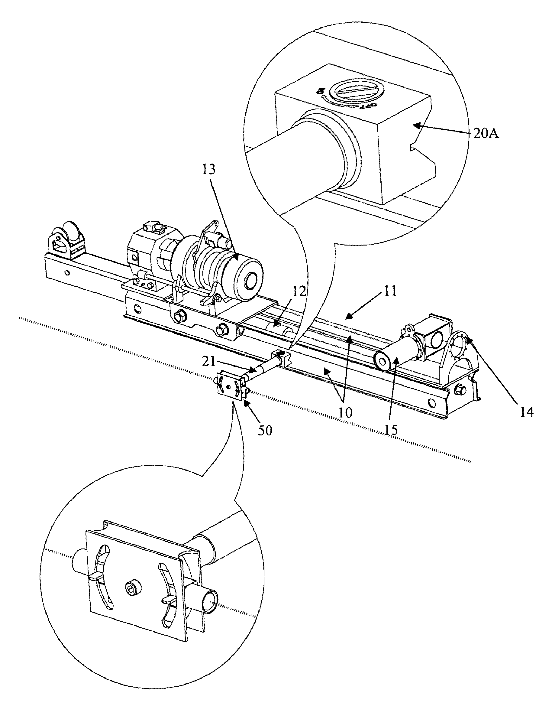
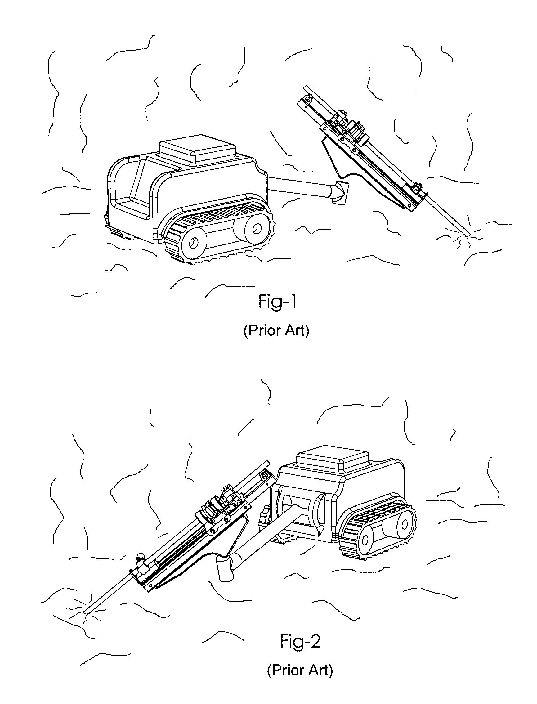
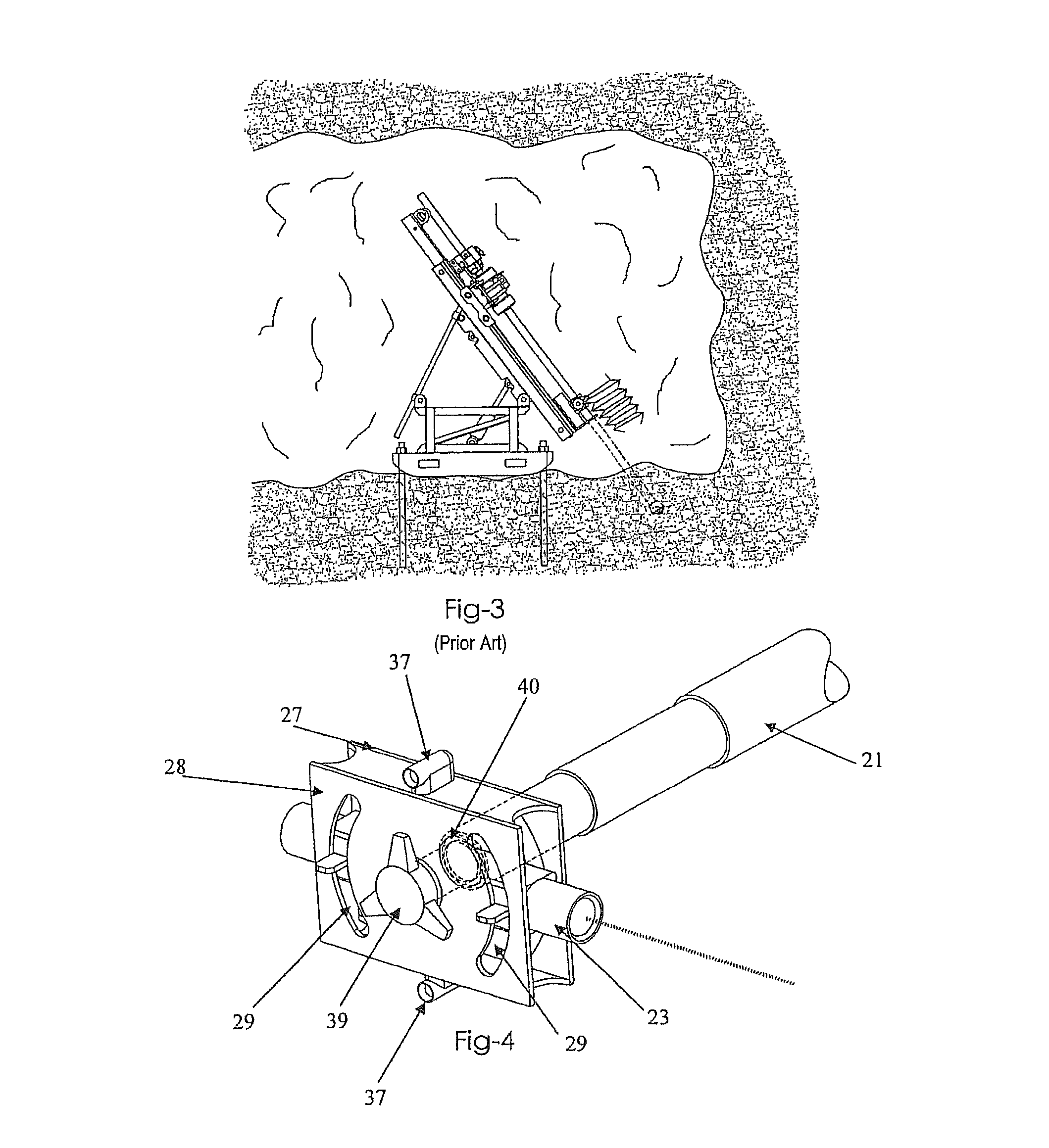
[0070]A conventional drill rig is illustrated in FIG. 3. The drilling rig itself is of a commercial type and basically comprises a pair of parallel steel feed rails 10 which will typically have a length of between 1.5 m up to 6 m. A carriage 11 slides over the top of each feed rail, and can reciprocate between the retracted position illustrated above and an extended position where the carriage has been moved to the front of the feed rails 10. A hydraulic ram 12 powers the carriage between its positions. On top of ...


PUM


Abstract

A laser alignment device for a drill rig having an elongate drill rod, the laser alignment device including a head unit having at least a pair of laser emitting devices mounted independently to one another thereon, each of the laser devices movable in one plane only and oriented in substantially opposite directions to one another, an attachment means to attach the head unit to a drill rig and a length adjustable assembly to adjust the separation distance between the head unit and the drill rod, wherein the alignment device is used to align at least the azimuth of the drill rod relative to survey marks.

Description

CROSS-REFERENCE TO RELATED APPLICATIONS[0001]This application claims the benefit of PCT International Patent Application No. PCT / AU2009 / 001467, filed Nov. 11, 2009, the disclosure of which is incorporated herein by reference.BACKGROUND OF THE INVENTION[0002]1. Field of the Invention[0003]The present invention relates to alignment devices and particularly to those which can be used to align drilling rigs to ensure correct drilling azimuth.[0004]2. Description of the Related Art[0005]In mining, whether underground or surface mining (e.g. diamond mining, goldmining etc), once the mine has been formed, exploratory drill holes are typically then formed to try to locate ore bodies. These drill holes can have a length of up to 1 km bur are usually much shorter.[0006]Initially, geologists will determine the likely location of an ore body or seam. The mine geologist will design the mine and the location of the exploratory holes and the surveyors will place survey markers in appropriate locat...

Claims


Application Information

Patent Timeline
Patent Type & Authority Patents(United States)
IPC IPC(8): E21B7/04G01B11/27E21B7/02E21B15/04E21B47/02G01C15/00
CPCE21B15/04E21B7/022E21B7/025G01C15/004G01B11/27E21B47/02
Inventor O'REILLY, JORDAN
Owner PRECISION ALIGNMENT HLDG
Why Eureka
Try Eureka