Light module for a motor vehicle headlamp, configured to generate a stripe-shaped light distribution

a technology for motor vehicles and light modules, which is applied in vehicle headlamps, fixed installations, lighting apparatus, etc., can solve the problems of limiting the variability of the lens system and obtaining limitation, and achieve high efficiency and high efficiency

Active Publication Date: 2015-06-02
AUTOMOTIVE LIGHTING REUTLINGEN GMBH
View PDF3 Cites 10 Cited by
  • Summary
  • Abstract
  • Description
  • Claims
  • Application Information

AI Technical Summary

Benefits of technology

[0018]With an adjacent configuration of the optical fiber configurations having a first optical fiber branch and a second optical fiber branch in a light module, the present invention enables the generation of a light distribution composed of individual stripes, which exhibits a pronounced intensity maximum at one narrow side of the stripe, and continuously diminishing intensity (and thus, a continuous decrease in the luminosity) of the stripe as the other narrow side is approached.
[0020]Another advantage of the light exit surface (which extends vertically) is that the secondary lens, which is downstream of the primary lens in the propagation direction of the light, can be smaller in this vertical axis than would be case without the vertical extension of the light exit surface of the primary lens. This is obtained by the Etandue conservation principle. In one embodiment, as a result of the improved vertical light bundling by the primary lens, the vertical height of a secondary lens can be reduced to 40 mm (values of 60-80 mm are known in the art).
[0022]These advantages are closely related to a high efficiency for the optical fiber branches used in the scope of the invention. These high efficiencies are obtained because the primary lens (or, the individual optical fiber branches of the primary lens, respectively) concentrate the light propagated therein efficiently, in order to generate a bundle from a light distribution of an LED according to the Lambert principle, which is concentrated onto a comparatively small light entry surface of a secondary lens that is, for example in one embodiment, 40 mm tall.

Problems solved by technology

This limitation is obtained in connection with the light sources normally available for use in motor vehicle headlamps, which have fixed dimensions in terms of their geometry and emit only limited luminous flux.
This requirement further limits the variability of the lens system.

Method used


Image

  • Light module for a motor vehicle headlamp, configured to generate a stripe-shaped light distribution
  • Light module for a motor vehicle headlamp, configured to generate a stripe-shaped light distribution
  • Light module for a motor vehicle headlamp, configured to generate a stripe-shaped light distribution

Examples


Embodiment Construction

)

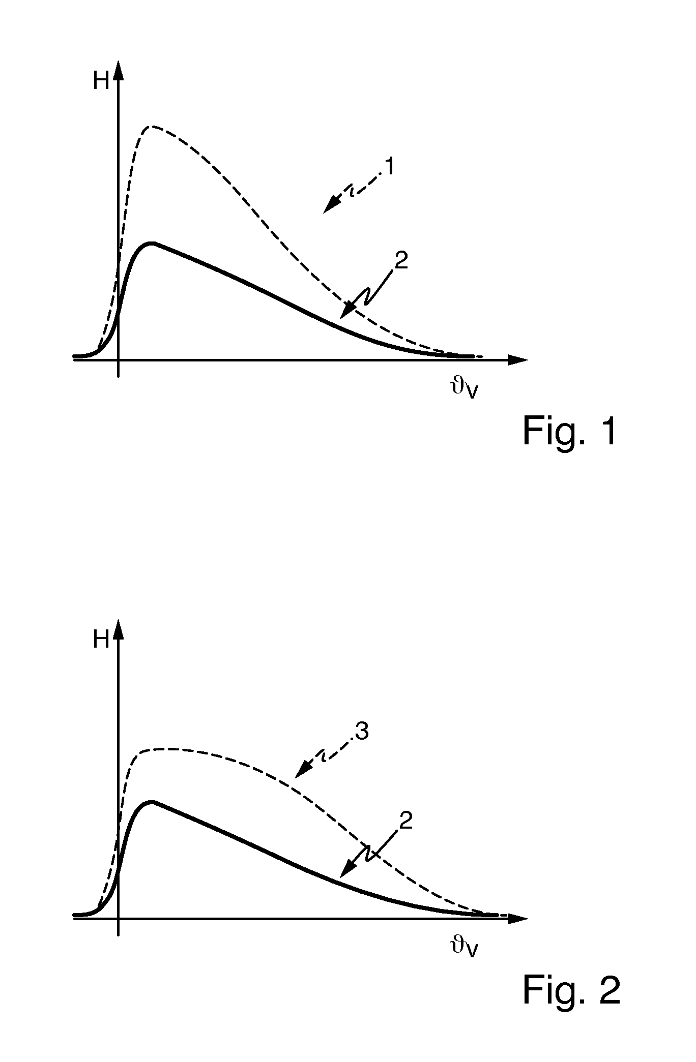
[0038]Elements that are the same, as well as those corresponding functionally to one another, are indicated by the same reference symbols throughout the figures. The curve indicated by a broken line in FIG. 1 represents a desired luminosity profile 1 of a stripe-shaped light distribution over the angle ΘV, as it is occurs in the region in front of the light module on a measurement screen disposed perpendicular to the main emission direction of the light module. This angle indicates an angular deviation in the vertical plane of a motor vehicle longitudinal axis with the designated use of the light module in a motor vehicle headlamp in a motor vehicle, which is located at the level of the horizon in front of the vehicle. The value ΘV=0 thus corresponds to the level of the horizon. In one embodiment, the desired light distribution of profile 1 exhibits practically no luminosity below the horizon, followed by a steep increase to a large maximum value (which occurs slightly above the ho...


PUM


Abstract

A light module for a motor vehicle headlamp having an optical fiber configuration with at least one first optical fiber branch and one second optical fiber branch. Each of the two branches has a light exit surface each bordered by two narrow sides and disposed such that a narrow side of the first branch is disposed parallel and directly adjacent to a narrow side of the light exit surface of the second branch. Each branch exhibits two transport surfaces. The transport surfaces exhibit surface norms having a directional component, which faces more toward a first narrow side of the two narrow sides of the branch than toward a second narrow side of the two narrow sides of the branch, wherein the narrow sides lying directly adjacent and parallel to one another are a second narrow side of the first branch and a first narrow side of the second branch.

Description

REFERENCE TO RELATED APPLICATION[0001]This application is based upon and claims priority to German Patent Application 10 2013 200 442.7 filed on Jan. 15, 2013.BACKGROUND OF INVENTION[0002]1. Field of Invention[0003]The invention relates to a light module for a motor vehicle headlamp.[0004]2. Description of Related Art[0005]A light module as depicted in published German Patent DE 10 2009 053 581 B3 is known in the art which exhibits an optical fiber configuration having at least one first optical fiber branch and a second optical fiber branch. Each of the two branches exhibit a light entry surface and a light exit surface, wherein in each case the light exit surface is bordered by two narrow sides and two long sides. The two branches are disposed such that a narrow side of the first branch is disposed parallel and directly adjacent to a narrow side of the light exit surface of the second branch. The narrow sides of the light exit surfaces of the two branches are of the same length, w...

Claims


Application Information

Patent Timeline
Patent Type & Authority Patents(United States)
IPC IPC(8): F21S8/10
CPCF21S48/17F21S48/1154F21S48/1241F21S41/143F21S41/24F21S41/60F21S41/663F21S41/153
Inventor STEFANOV, EMIL P.BUCHBERGER, CHRISTIANVOGT, HENNING
Owner AUTOMOTIVE LIGHTING REUTLINGEN GMBH
Why Eureka
Try Eureka