Projectile assembly with stabilization/obturation enhancement

a projectile and stabilizer technology, applied in the field of projectiles, can solve the problems of projectile rotation out of alignment with the longitudinal axis, and achieve the effects of reducing obliterated sabots, minimizing or controlling the deformation of the projectile seating base, and increasing accuracy

Active Publication Date: 2015-06-02
FEDERAL CARTRIDGE
View PDF22 Cites 8 Cited by
  • Summary
  • Abstract
  • Description
  • Claims
  • Application Information

AI Technical Summary

Benefits of technology

[0016]An embodiment of the invention is a method of manufacturing a shotgun shell with a slug. The method comprises injection molding a sabot having a base at a rearward end, foldable petals extending forwardly from the base, and a central recess at the rearward end of the base. Further the method comprises inserting a pusher plate with a central axial post into the central recess. The method further comprises installing a slug in the sabot, installing propellant, wading, and the sabot with the slug into a shotgun shell casing. A feature and advantage of the invention is that assembly steps and complexity of the manufacture is reduced and the shotgun shell performance is increased compared to other prior art configurations of shotgun shells with metal plates embedded in the sabot.
[0017]In one aspect, conventional shotgun shell components, including conventional sabots and conventional projectiles, can be assembled in accord with the invention by insertion of the projection of the pusher plate into the rear surface of the projectile seating base and then otherwise conventionally assembled. In one aspect, the conventional wadding may be slightly shortened axially to accommodate the thickness of the pusher plate. A feature and advantage of embodiments of the invention is that this inexpensive additional component provides increased accuracy and reduces obliterated sabots.
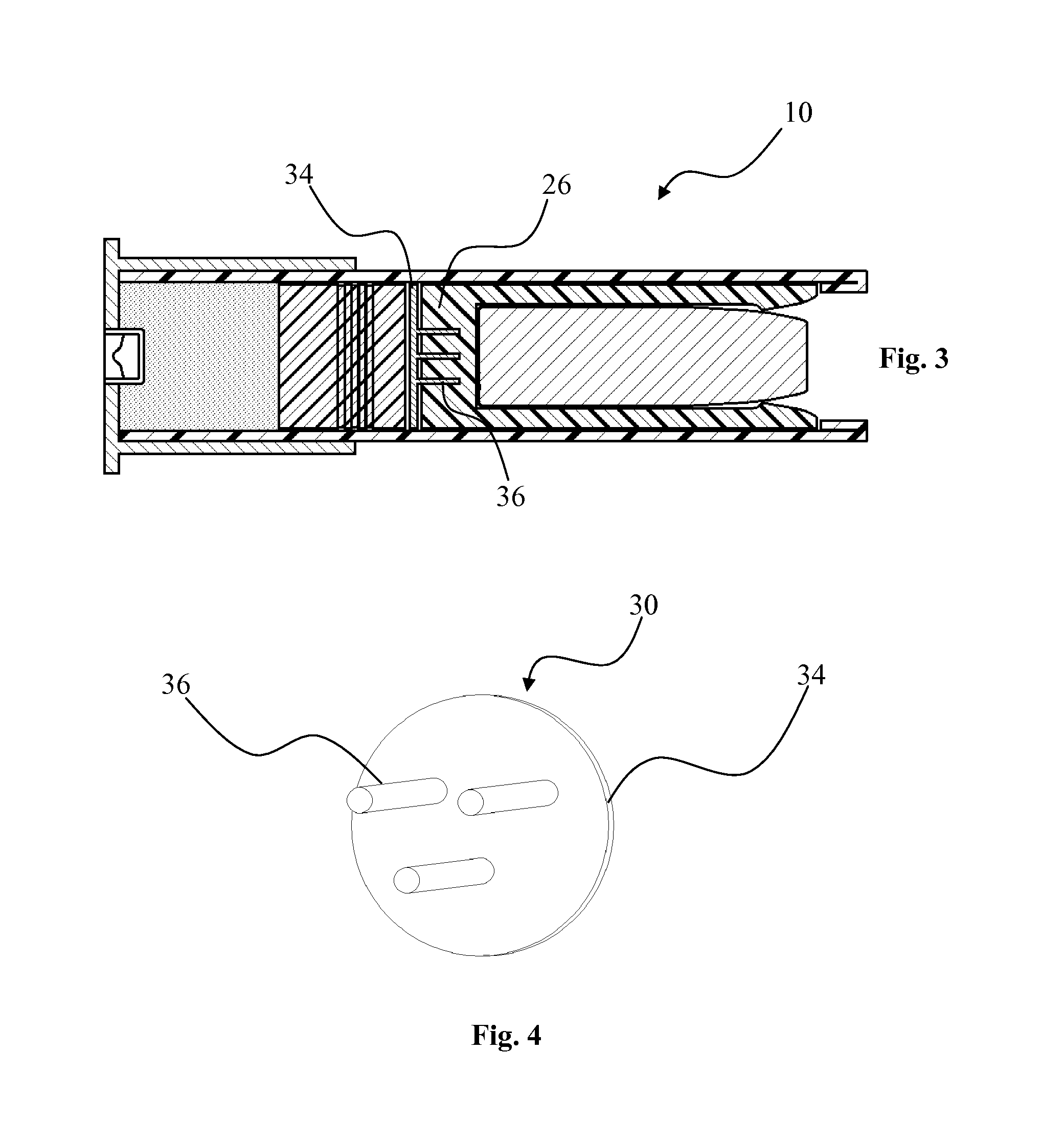
[0018]A polymer sabot, according to an embodiment of the present invention, comprises a pusher plate with a forward extending axial projection that controls the application of force to the projectile seating base to minimize or control the deformation of the projectile seating base and can practically eliminate excess deformation or failure of the sabot. The pusher plate is positioned against the rear of the projectile seating base and comprises at least one projection extending axially into the projectile seating base. The projection can be sized such that the end of the projection is proximate the rear of the projectile once the projectile is seated on the polymer base. The projection comprises a rigid material to reduce axial compression of the polymer base as a result the opposing setback and propellant forces. The projection can also comprise a heat insensitive material to maintain the shape of the projectile seating base when the projectile seating base is exposed to high temperatures. In one aspect, several projections can be spaced around the central longitudinal axis of the sabot to prevent misalignment of the projectile as the projectile seating base is compressed.
[0019]A sabot assembly, according to an embodiment of the present invention, comprises a sabot and a pusher plate. The sabot comprises a projectile seating base and at least two wings or petals extending from the base portion. The projectile seating base defines a seat that cooperates with the wings or petals to form a cup for receiving a projectile. The pusher plate is positioned against the rear of the projectile seating base and further comprises at least one projection extending axially into the base portion. In one aspect, the diameter of the pusher plate can approximate the diameter of the polymer projectile seating base such that the majority or all of force generated by the ignited propellant is transferred to the pusher plate rather than polymer base portion. A feature and advantage of particular embodiments with forward axially extending projections, recesses for receiving the axially extending projections can be preformed in the projectile seating base to facilitate manufacture and assembly of a sabot / pusher plate assembly.
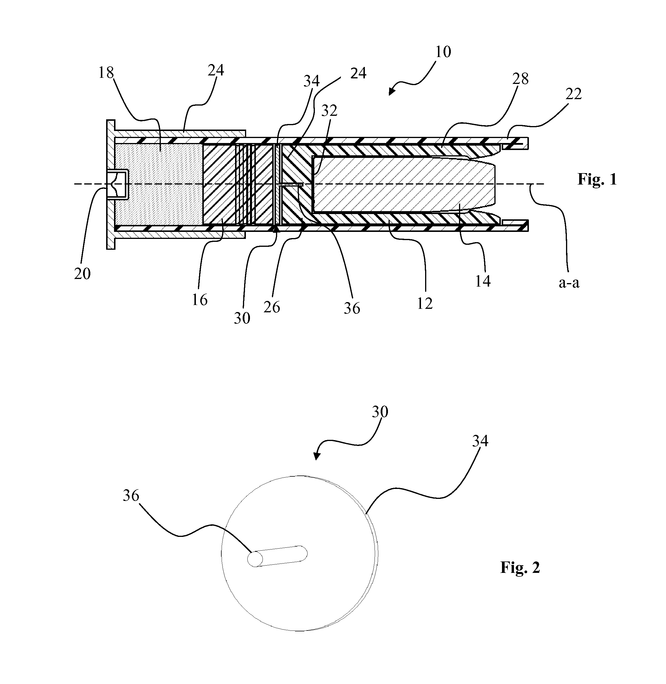
[0020]In an embodiment of the invention, a wobble stabilizing assembly comprising a cylindrical polymer portion with a central axis, a forward end and a rearward end, a disc with a central axially extending prong or post is positioned at the rearward end of the cylindrical polymer portion with the prong or post extending into the cylindrical polymer portion. The disc extends perpendicularly to the axially extending prong or post and is fixed thereto. The cylindrical polymer portion is positioned behind, directly engaged with or spaced from, a projectile to be fired. The propellant positioned rearwardly of the wobble stabilizing assembly, either in direct contact or spaced therefrom. Upon firing the axial compression of the cylindrical polymer portion is controlled to be uniform by way of the disc and central axial post fixed thereto. In embodiments of the invention the cylindrical polymer portion may have a central recess on the rearward side to receive the projection during an assembly step. The recess may also be tapered such that the outward radial expansion of the cylindrical polymer
[0021]In an embodiment of the invention, an obturation enhancement assembly comprising a cylindrical polymer base with a central axis, a forward end and a rearward end, a disc with a central axially extending projection is positioned at the rearward end of the cylindrical polymer base with the projection extending into the cylindrical polymer base. The periphery of the disc is in a plane perpendicular to the axially extending projection and is fixed thereto, such as being unitary or a press fit. The cylindrical polymer portion is positioned behind, directly engaged with or spaced from, a projectile to be fired in a barrel. The propellant positioned rearwardly of the wobble stabilizing assembly, either in direct contact or spaced therefrom. Upon firing the axial compression of the cylindrical polymer portion is controlled to be uniform to provide uniform radial expansion of the cylindrical polymer portion around the entire circumference of the cylindrical polymer portion by way of the disc and central axial post fixed thereto.

Problems solved by technology

The inventors found that non-uniform axial deformation and / or disintegration of the projectile seating base during firing causes the projectile to rotate out of alignment with longitudinal axis defined by the barrel of the firearm.

Method used


Image

  • Projectile assembly with stabilization/obturation enhancement
  • Projectile assembly with stabilization/obturation enhancement
  • Projectile assembly with stabilization/obturation enhancement

Examples


Embodiment Construction

[0063]As shown in FIGS. 1, 3, 5 and 7, a cartridge 10, according to an embodiment of the present invention, comprises a sabot 12, a projectile 14, wadding 16, a propellant charge 18 and a primer 20. The sabot 12 generally defines a cup for receiving the projectile 14. As depicted, the projectile 14 comprises a shotgun slug, but can comprise a bullet or any other conventional projectile deployable from the sabot 12. The wadding 16 is positioned forward of the propellant charge 18 to transfer the propellant force created by the expanding gases from the propellant charge 18. The primer 20 is positioned to be struck by the firing pin of the firearm to ignite the propellant charge 18. As depicted, the cartridge 10 is a shotgun shell and further comprises a casing 22 and a brass head 24. The casing 22 defines an enclosable cylinder for receiving the sabot 12, projectile 14, wadding 16 and the propellant charge 18. The brass head 24 reinforces the end of the casing 22 containing the propel...


PUM


Abstract

A projectile assembly comprises a base portion for receiving projectiles such as slugs and has an associated pusher plate at a rear end thereof for minimizing or controlling deformation of the rear end of the base portion during firing. The pusher plate has a disc with one or more axially extending projections that extend axially into the rearward end of the base portion thereby reinforcing the base portion and upon firing providing uniform axial deformation and / or obturation of the base portion with respect to a firearm barrel. The projectile assembly may be, for example, part of a shotgun shell slug cartridge, and provides enhanced accuracy over the prior art.

Description

FIELD OF THE INVENTION[0001]The present invention is generally directed towards projectiles, such as slugs with polymer projectile seating bases, for example a sabot with a projectile seating base, and means for enhancing the performance thereof.BACKGROUND OF THE INVENTION[0002]Slugs or bullets fired from shotguns fitted with rifled barrels or from muzzleloaders are often fitted with a sabot that releases the slug or bullet as the projectile exits the muzzle of the firearm. Sabots significantly improve the range and accuracy of the projectile by engaging the rifling of the barrel to impart spin to the projectile and also seal the barrel around the projectile to prevent leakage of the generated propellant gasses around the projectile. Sabots for small arms, such as shotgun slugs or for muzzleloaders, typically comprise a plurality of wings extending from a base portion configured as a projectile seating base on which the projectile is seated. Prior to firing, the wings are folded for...

Claims


Application Information

Patent Timeline
Patent Type & Authority Patents(United States)
IPC IPC(8): F42B14/06F42B5/02F42B7/08F42B7/10
CPCF42B14/064F42B5/02F42B7/08F42B7/10
Inventor PETERSON, BRYAN P.CARLSON, ERIK K.MOSER, ADAM J.HEAD, LAWRENCE P.
Owner FEDERAL CARTRIDGE
Why Eureka
Try Eureka