Method and apparatus for detecting RF field strength
What is Al technical title?
Al technical title is built by PatSnap Al team. It summarizes the technical point description of the patent document.
a technology of rf field and detection method, applied in the direction of mechanical actuation of burglar alarms, transmission monitoring, instruments, etc., to avoid unnecessary proliferation of numbers
Active Publication Date: 2015-06-02
RFMICRON
View PDF5 Cites 27 Cited by
Summary
Abstract
Description
Claims
Application Information
AI Technical Summary
This helps you quickly interpret patents by identifying the three key elements:
Problems solved by technology
Method used
Benefits of technology
Problems solved by technology
Furthermore, it is of no relevance in such systems which specific voltage levels are selected to represent each of the logic states.
Method used
Image
Click on the blue label to locate the original text in one second.
Reading with bidirectional positioning of images and text.
Examples
Embodiment Construction
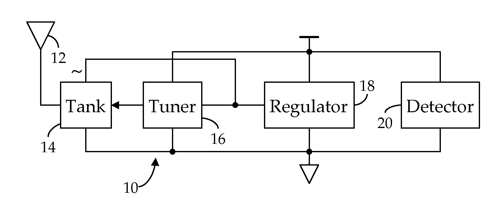
[0024]Shown in FIG. 1 is an RF receiver circuit 10 suitable for use in an RFID application. As we have described in our Related References, an RF signal electromagnetically coupled to an antenna 12 is received via a tank circuit 14, the response frequency, fR, of which is dynamically varied by a tuner 16 to better match the transmission frequency, fC, of the received RF signal, thus obtaining a maximum power transfer. In particular, as further noted in the Related Applications, the RMS voltage induced across the tank circuit 14 by the received RF signal is quantized by tuner 16 and the developed quantization employed to control the impedance of the tank circuit 14. As also described in the Related References, the unregulated, AC current induced in the tank circuit 14 by the received RF signal is conditioned by a regulator 18 to provide regulated DC operating power to the receiver circuit 10. In accordance with our present invention, we now provide a field strength detector 20, also ...
PUM
Abstract
A method and apparatus for detecting RF field strength. A field strength reference generator develops a field strength reference current as a function of a field strength of a received RF signal; and a field strength quantizer develops a digital field-strength value indicative of the field strength reference current. In one embodiment, detected field strength is used to dynamically vary the impedance of a tank circuit whereby, over time, induced current is maximized. In another embodiment, using the quantized field strength to sense changes to the environment to which the RFID tag is exposed.
Description
CROSS-REFERENCE TO RELATED APPLICATIONS[0001]This application claims priority to U.S. Provisional Application Ser. No. 61 / 428,170 filed 29 Dec. 2010 (“Parent Provisional One”), and U.S. Provisional Application Ser. No. 61 / 485,732 filed 23 May 2011, (“Parent Provisional Two”), collectively, “Parent References”, and hereby claims benefit of the filing dates thereof pursuant to 37 CFR 1.78(a)(4).[0002]This application is a Continuation-In-Part of application Ser. No. 12 / 462,331, filed 1 Aug. 2009 (“Related Application”), now U.S. Pat. No. 8,081,043, issued 20 Dec. 2011; which is in turn a Division of application Ser. No. 11 / 601,085, filed 18 Nov. 2006, now U.S. Pat. No. 7,586,385, issued 8 Sep. 2009 (“Related Patent”) (collectively, “Related References”). The subject matter of the Related References, each in its entirety, is expressly incorporated herein by reference.[0003]This application is related to application Ser. No. 13 / 209,420, filed simultaneously herewith on 14 Aug. 2011 (“Re...
Claims
Application Information
Patent Timeline
Application Date:The date an application was filed.
Publication Date:The date a patent or application was officially published.
First Publication Date:The earliest publication date of a patent with the same application number.
Issue Date:Publication date of the patent grant document.
PCT Entry Date:The Entry date of PCT National Phase.
Estimated Expiry Date:The statutory expiry date of a patent right according to the Patent Law, and it is the longest term of protection that the patent right can achieve without the termination of the patent right due to other reasons(Term extension factor has been taken into account ).
Invalid Date:Actual expiry date is based on effective date or publication date of legal transaction data of invalid patent.