LED luminaire driving circuit with high power factor

Active Publication Date: 2015-06-02
NAT CHUNG SHAN INST SCI & TECH
View PDF4 Cites 16 Cited by
  • Summary
  • Abstract
  • Description
  • Claims
  • Application Information

AI Technical Summary

Benefits of technology

The present invention provides an LED luminaire driving circuit with high power factor and integrated with a zero current detecting unit, a feedback unit, and an error amplifier unit without using any input-end voltage detecting signal. This circuit can be used for driving high power LED lamps without producing any extra power consumption. Additionally, the LED luminaire driving circuit does not include any optocoupler feedback circuits, reducing the manufacturing cost of the circuit. The circuit performs stable output voltage and current signals to the load end and has excellent stability and current modulation error rate.

Problems solved by technology

In spite of that, the constant-frequency control flyback converter 1e still includes the following drawbacks: the entire manufacturing cost of the constant-frequency control flyback converter 1e is too expensive because the disposing of the opticalcoupler feedback circuit 13e.

Method used


Image

  • LED luminaire driving circuit with high power factor
  • LED luminaire driving circuit with high power factor
  • LED luminaire driving circuit with high power factor

Examples


Embodiment Construction

[0037]To more clearly describe an LED luminaire driving circuit with high power factor according to the present invention, embodiments of the present invention will be described in detail with reference to the attached drawings hereinafter.

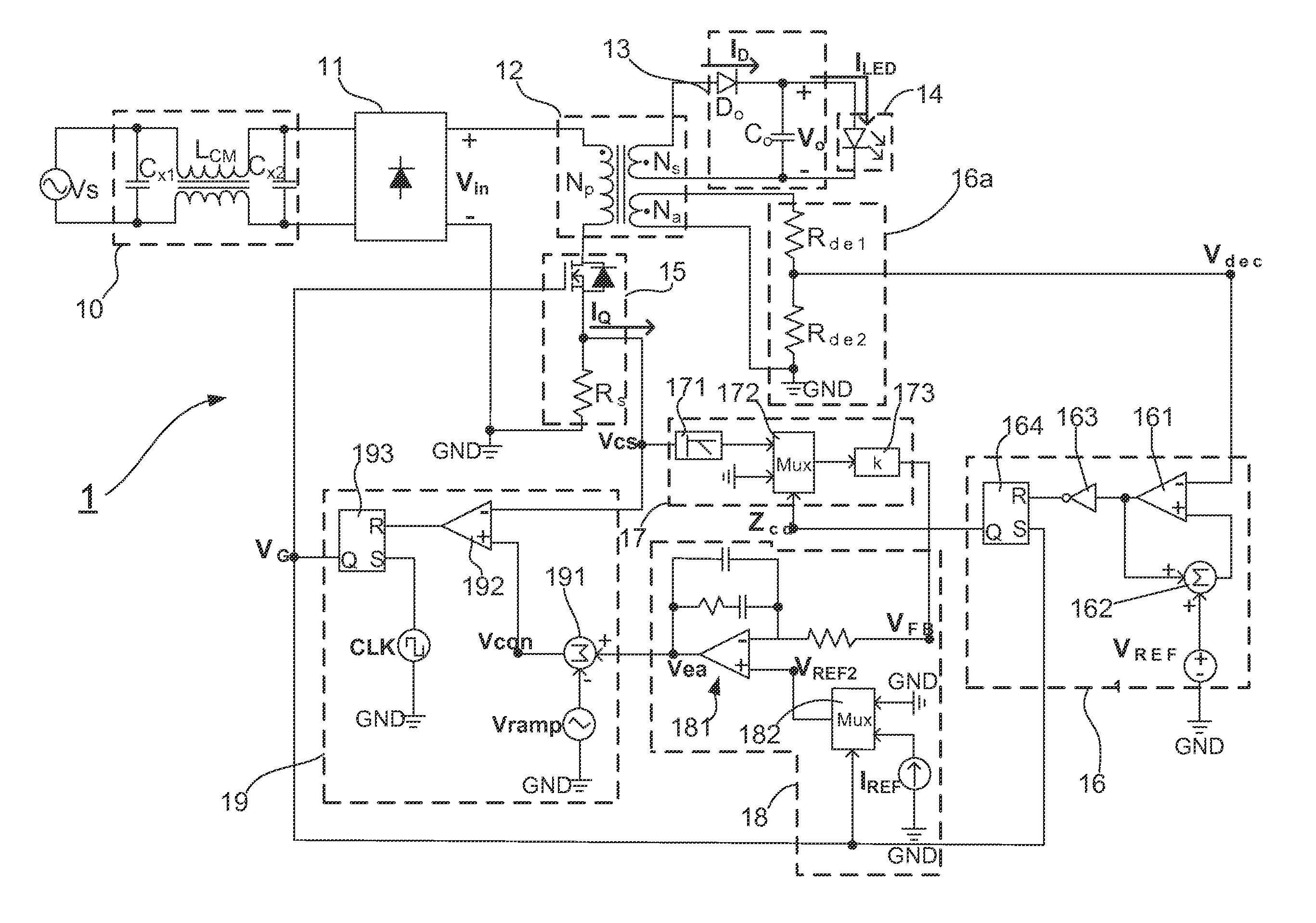
[0038]With reference to FIG. 6, there is shown a circuit block diagram of an LED luminaire driving circuit with high power factor according to the present invention. As shown in FIG. 6, the LED luminaire driving circuit 1 of the present invention includes: a filter unit 10, a rectifier unit 11, a transformer unit 12, an output unit 13, a power switch unit 15, a zero current detecting unit 16, a feedback unit 17, an error amplifier unit 18, and a power switch driving unit 19.

[0039]Referring to FIG. 6 again, and please simultaneously refer to FIG. 7, which shows a circuit framework diagram of the LED luminaire driving circuit with high power factor. As shown in FIG. 6 and FIG. 7, the filter unit 10 is coupled to an input source VS for receiving an A...


PUM


Abstract

The present invention relates to an LED luminaire driving circuit with high power factor, comprising: a filter unit, a rectifier unit, a transformer unit, a power switch unit, a zero current detecting unit, a feedback unit, an error amplifier unit, and a power switch driving unit. Particularly, the LED luminaire driving circuit proposed by the present invention does not include any optocoupler feedback circuits, so it is able to effectively reduce the entire circuit manufacturing cost of this LED luminaire driving circuit. Moreover, this LED luminaire driving circuit can selectively work under CCM operation or DCM operation with high power factor (PF˜1), and provide stable output voltage signal and output current signal to load end. In addition, this LED luminaire driving circuit performs excellent stability and current modulation error rate (<±3%).

Description

BACKGROUND OF THE INVENTION[0001]1. Field of the Invention[0002]The present invention relates to the technology fields of LED luminaire driving circuits, and more particularly to an LED luminaire driving circuit with high power factor.[0003]2. Description of the Prior Art[0004]Recently, light-emitting diodes (LEDs) are widely applied to be the lighting device in human life. And currently, more and more families replace the traditional fluorescent lamps by LED lamps due to the issue of Energy Conservation and Carbon Reduction is more and more popular. However, since the power formation of the market electricity is AC power and the LED lamps are driven to emit light by DC power, it is necessary to dispose a power converting device between the market electricity and the LED lamps for converting the AC power to DC power.[0005]With reference to FIG. 1, there is shown a circuit framework diagram of a BCM flyback converter with variable frequency control. The BCM (Boundary Conduction Mode)...

Claims


Application Information

Patent Timeline
IPC IPC(8): G05F1/00H05B44/00
CPCH05B33/0815H05B33/0845H05B45/10H05B45/385
Inventor CHIANG, HSUANG-CHANGMA, CHAO-TSUNGCHEN, KUN-FENGHUANG, YING-SUN
Owner NAT CHUNG SHAN INST SCI & TECH
Why Eureka
Try Eureka