
Cooperative beamforming apparatus and method in wireless communication system

a wireless communication system and beamforming technology, applied in the field of cooperative beamforming apparatus and wireless communication system, can solve the problems of inability to expect inability to improve with the cost of tiny increase of information exchange, and difficulty in estimating the improvement of equivalent channel condition, etc., to achieve the effect of increasing the feedback burden of mobile stations

Active Publication Date: 2015-06-09
SAMSUNG ELECTRONICS CO LTD
View PDF13 Cites 0 Cited by
  • Summary
  • Abstract
  • Description
  • Claims
  • Application Information

AI Technical Summary

Benefits of technology

This approach enables cooperative beamforming in the downlink direction without increasing feedback load for mobile stations and achieves SINR improvement without the need for costly cooperative network implementations, simplifying the network structure.

Problems solved by technology

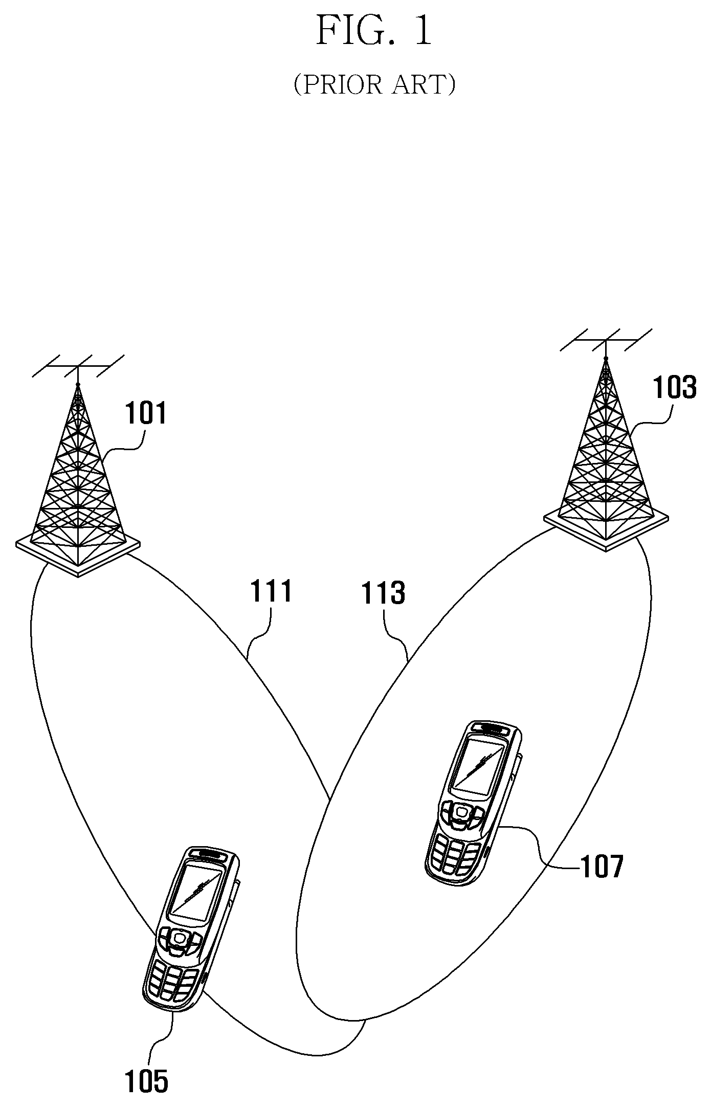
Typically, in the cellular communication system, a user experiences low Signal To Interference and Noise Ratio (SINR) at the cell boundary far from the serving base station due to the signal loss and neighbor cell interferences.
Historically, handover has been considered mainly as an issue related to mobility, however, various researches are conducted recently to improve the communication stability at the cell boundary areas of bad channel conditions.
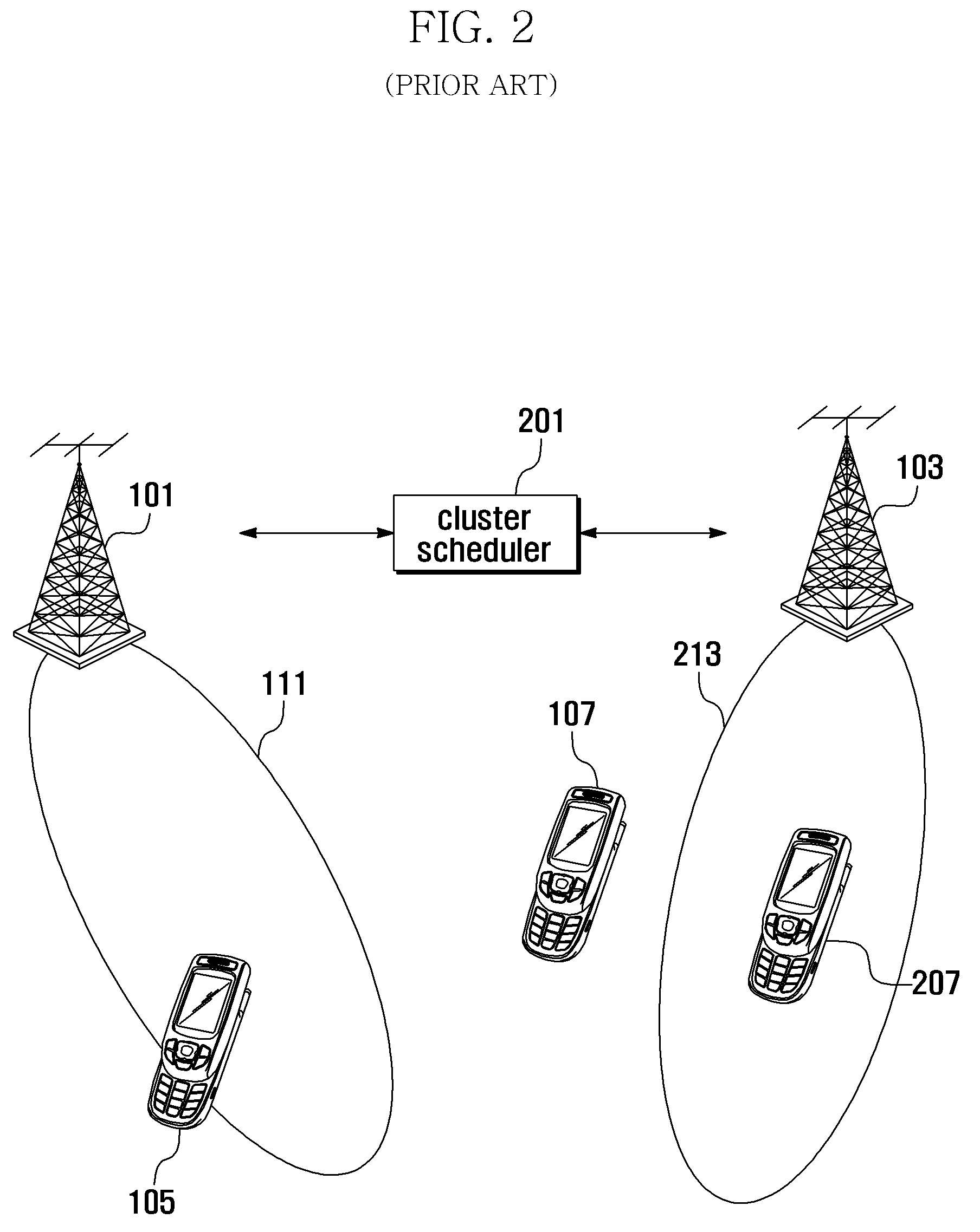
In the latter case, it is difficult to expect the improvement of the equivalent channel condition to that extent in the former case, but any improvement with the cost of tiny increase of information exchange between the base stations.
This means that the independent beamforming of the base stations do not guarantee the SINR improvement for the mobile station.
However, the conventional cooperative network does not help improving the uplink SINR of the mobile station at the cell boundary area.
Furthermore, transmitting additional feedback information, i.e. PMI intended not to be used by the neighbor base station, as well as the CQI and PMI intended to be used by the serving base station must be burdensome from the viewpoint of the mobile station located at the cell boundary area.
That is, the conventional cooperative network must pay significant cost in uplink direction for improving the SINR in downlink direction.

Method used


Image

  • Cooperative beamforming apparatus and method in wireless communication system
  • Cooperative beamforming apparatus and method in wireless communication system
  • Cooperative beamforming apparatus and method in wireless communication system

Examples


Embodiment Construction

[0038]Exemplary embodiments of the present invention are described with reference to the accompanying drawings in detail. The same reference numbers are used throughout the drawings to refer to the same or like parts. Detailed descriptions of well-known functions and structures incorporated herein may be omitted to avoid obscuring the subject matter of the present invention.

[0039]Wireless communication systems are evolving to meet the requirements for wireless packet data communication system for high speed and high quality multimedia services including data and video as well as convention voice. Recently, various wireless communication standards and technologies such as High Speed Downlink Packet Access (HSDPA) and High Speed Uplink Packet Access (HSUPA) of the 3rd Generation Partnership Project (3GPP), High Rate Packet Data (HRPD) of 3GPP2, and 802.16x of Institute of Electrical and Electronics Engineers (IEEE) have been developed for supporting high speed and high quality radio p...


PUM


Abstract

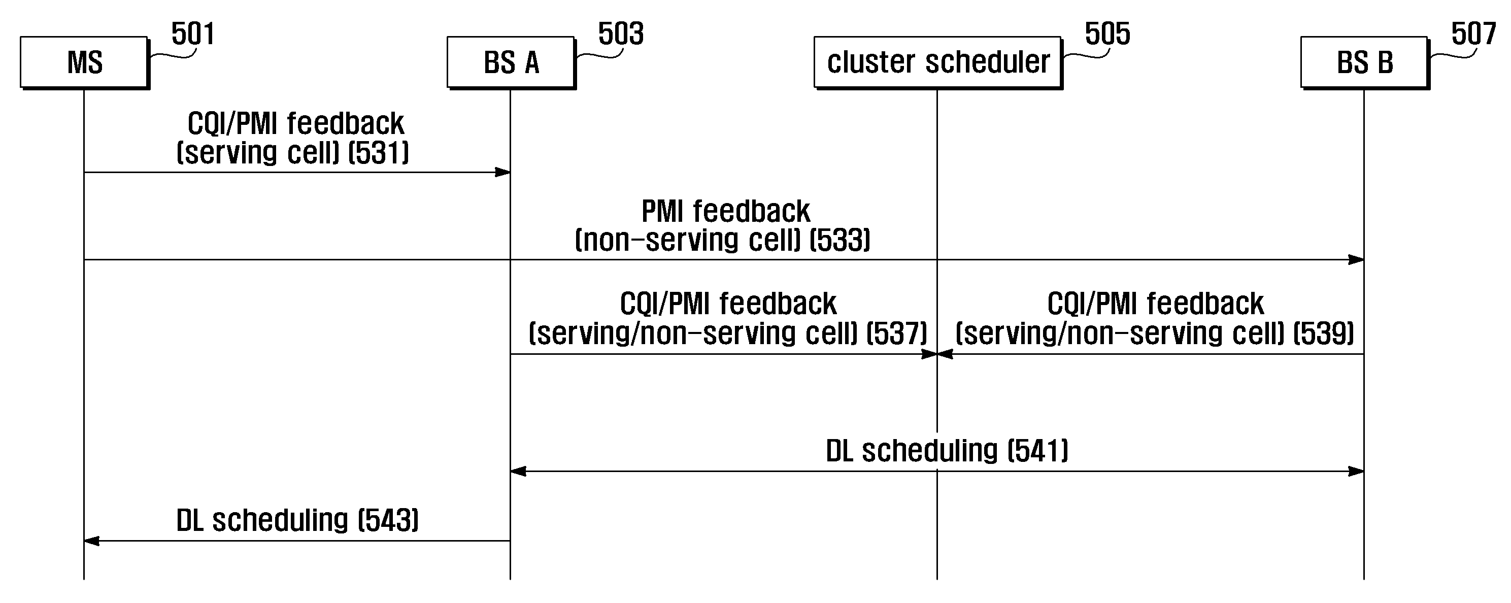
A cooperative beamforming apparatus and method in a wireless communication system supporting channel sensitive scheduling based on feedback information is provided. A beamforming method in a wireless communication system according to the present invention includes transmitting, at a mobile station, a channel condition information of a channel of a serving base station to the serving base station and a channel condition information of a channel of a neighbor base station; and forming, at the serving base station, a beam based on the channel condition information to transmit a signal and, at the neighbor base station, a beam to transmit a signal.

Description

TECHNICAL FIELD[0001]The present invention relates to wireless communications and, in particular, to a cooperative beamforming apparatus and method in a wireless communication system supporting channel sensitive scheduling based on feedback information.BACKGROUND ART[0002]Cellular structure is a basic principle for the configuration of the radio subsystem of a mobile communication system, and the service coverage of the system can be expanded by addition of base stations.[0003]Typically, in the cellular communication system, a user experiences low Signal To Interference and Noise Ratio (SINR) at the cell boundary far from the serving base station due to the signal loss and neighbor cell interferences. In order to maintain the ongoing service in such a situation, it is required to reduce the amount of transmission data or increase resources such as frequency, time, and transmission power as compared to the near users.[0004]Meanwhile, the cellular communication system supports handove...

Claims


Application Information

Patent Timeline
Patent Type & Authority Patents(United States)
IPC IPC(8): H04J11/00H04L27/28H04B7/02H04W4/00H04W16/28
CPCH04W16/28H04B7/024
Inventor HAN, JIN KYUCHO, JOON YOUNGLEE
Owner SAMSUNG ELECTRONICS CO LTD
Learn More