Device and method for treating a chronic total occlusion

a total occlusion and device technology, applied in the field of recanalizing devices and blood vessels, can solve the problems of chronic total occlusions that can have serious medical consequences, inadequate support of dependent organ functions, and barely provide enough blood flow to keep the end organ alive, so as to prevent vessel damage, prevent blood vessel damage, and restore normal circulatory function

Active Publication Date: 2015-06-23
ANGIOSAFE
View PDF21 Cites 10 Cited by
  • Summary
  • Abstract
  • Description
  • Claims
  • Application Information

AI Technical Summary

Benefits of technology

[0016]The present invention provides a device and method for treatment of vascular occlusions. It is an object of the invention to disrupt vascular occlusions or other blockages formed within blood vessels in order to provide pathways for the placement of guidewires, interventional devices and catheters as part of an overall effort to restore normal circulatory function having the advantages of a reinforced inner tube, easy controllability and a shape that prevents vessel damage but maximizes occlusion fracturing.
[0018]In one aspect of the invention, the inner tubular member is reinforced with one or more helically coiled wires. Preferably two helically coiled wires encircle the inner tubular member in a double helix fashion and are secured (by polymer glue or another securing substance) to the outer surface of the inner tubular member. The helically wrapped wire(s) allows flexibility of the main body to curve within the blood vessel lumen, and conform to the pathway of the blood vessel. Having wire(s) encircle the inner tubular member has the advantage of strengthening the shaft of the main body, such that the main body will not kink when curving along the pathway of the blood vessel. The coiled wires also have the advantage of improving steerability and pushability of the main body when advanced inside a diseased blood vessel or inside a hard fibrocalcific plaque of the occlusion.
[0019]In another aspect of the present invention, the device has an expandable material, such as a balloon, that envelops at least a portion of the main body and surrounds the outer tubular member of the main body. The distal end of the balloon is proximal to the outer loops. Configured in this way, when the balloon is inflated, the balloon presses against the vessel walls and centers the main body of the device to the center of the vessel. The use of an inflatable balloon therefore has the advantage of centering the main body so that mechanical fracturing of the occlusion occurs near the center of the vessel, thus preventing unwanted veering of the main body and distal end of the device into a vessel wall.
[0021]In another embodiment, the CTO device has a motor unit to aid in rotating the main body and / or drilling tip. The motor unit has an electric motor to provide torque to the main body which spins the pairs of opposing loops to fracture the CTO and threaded inner and out motor unit tubular bodies. The motor unit is connected to the main body via these motor unit inner and outer tubular members. To aid in rotation of main body, the motor unit tubular members have helically threaded grooved surfaces so that when an electric motor turns the tubular members, rotational force can be translated into a linear force, which can drive the distal end of the device through a CTO. A locking screw may lock the motor unit to the main body.
[0024]An advantage of the main body separated into a stationary unit and a drilling unit is that only the small rotating portion of the main body (i.e. the drilling unit) rotates, instead of the entire main body rotating. A small rotating unit prevents unintended damage that may occur if the device rotates against a vessel wall, which would cause additive frictional forces that damage vessel walls.
[0026]In another aspect of the invention a motor sensor is incorporated into the distal end of the main body of the drilling unit, and a microprocessor is incorporated into the motor unit. The microprocessor acquires and analyzes data sent from the sensor about the motion of the drilling unit, and in turn sends commands to the motor unit that that operator is guiding. In this way, the speed and character of rotation of the distal end of the device or drilling unit can be more precisely controlled by the operator to suit CTO lesion characteristics.

Problems solved by technology

However these collateral vessels barely provide enough blood flow to keep the end organs alive and are inadequate to support the function of dependent organs.
Chronic total occlusions can have serious medical consequences depending on their location.
For example, blockages located in coronary arteries can cause heart muscle damage and heart failure, whereas blockages located in femoral and popliteal arteries can cause leg ulcers and gangrene.
CTO lesions frequently contain extremely hard and calcified plaques, which makes them impenetrable.
Guidewires, when used in CTOs, are sometimes risky as they can inadvertently damage or more ominously perforate the vessel wall.
Often, the guidewire tip has insufficient support, and can buckle during an attempted penetration into the calcified plaque.
The guidewire, when forced into a CTO, can also inadvertently be misdirected by the operator in an unintended direction, creating a dead end plane between the vessel wall and the plaque (i.e. a subintimal plane).
If the guidewire fails to create successful passage through the CTO, the resulting subintimal tract prohibits the use of subsequent therapeutic devices such as a balloon, stent or atherectomy catheter.
Another drawback in CTO devices includes shafts that are not robust enough to resist kinks when advanced inside of a CTO.
Still another drawback is that the CTO device is not easily controlled, whereby the tip of the CTO device veers eccentrically away from the center of the blood vessel when the CTO device is pushed though the CTO.
Due to these drawbacks, success rates with guidewires in CTO revascularization are marginal at best.
In addition, costs, cumbersomeness, need for complex preparation and lengthy training required for proper usage of these CTO devices can prohibit their widespread and cost efficient usage.

Method used


Image

  • Device and method for treating a chronic total occlusion
  • Device and method for treating a chronic total occlusion
  • Device and method for treating a chronic total occlusion

Examples


Embodiment Construction

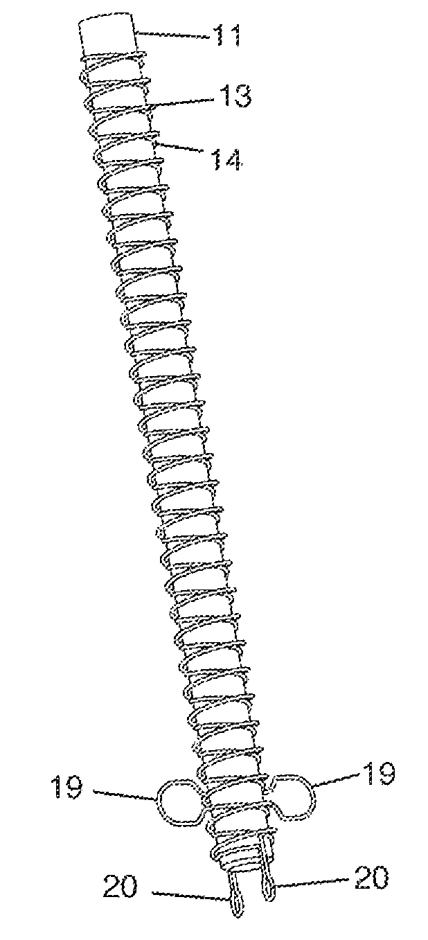
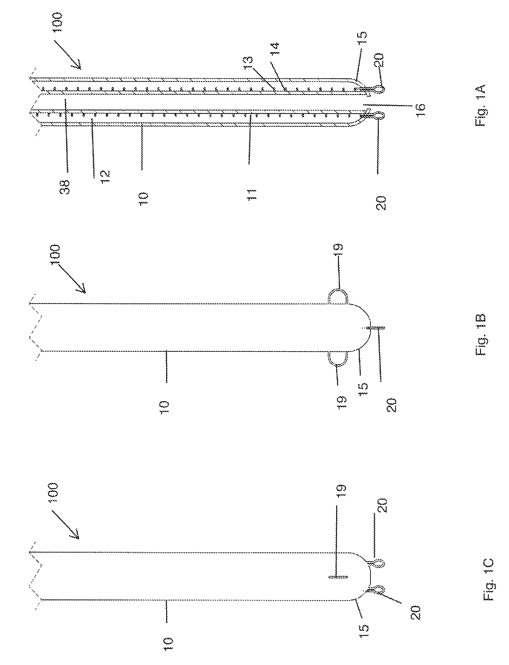
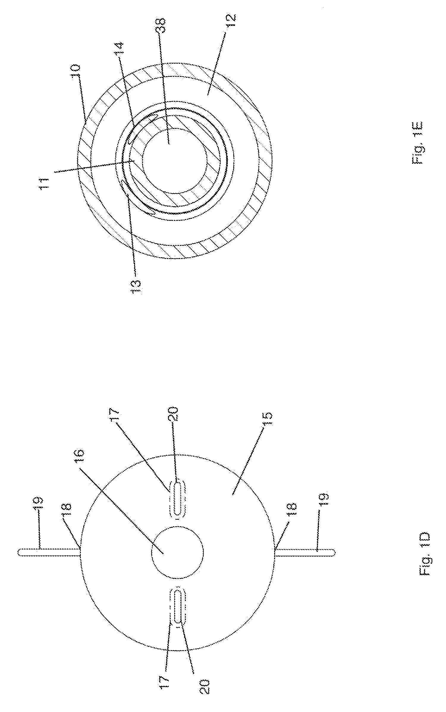
[0054]The invention now will be described more fully hereinafter with reference to the accompanying drawings, in which embodiments of the invention are shown. This invention may, however, be embodied in many different forms and should not be construed as limited to the embodiments set forth herein. Rather, these embodiments are provided so that this disclosure will be thorough and complete, and will fully convey the scope of the invention to those skilled in the art. Although the description of the invention is in the context of treatment of blood vessels, the invention may also be used in any other body passageways where it is deemed useful.

[0055]It will be understood that when an element is referred to as being “on” another element, it can be directly on the other element or intervening elements may be present there between. As used herein, the term “and / or” includes any and all combinations of one or more of the associated listed items.

[0056]It will be understood that, although t...


PUM


Abstract

A device and method for opening blood vessel blockages, such as chronic total occlusions, is disclosed. The device has a main body and motor unit. The main body has an inner tubular member disposed inside an outer tubular member. The inner tubular member is reinforced with hydrophilic polymer coated wires, which are drawn out into two pairs of loops at the distal end of the device. The motor unit also has an inner tubular member disposed within an outer tubular member. The motor unit is used to create torque to rotate the main body having the pairs of loops. When torque transmitted to main body, the device spins. As the device is advanced through a blood vessel, the rotating loops penetrate and break down the occlusion, and recanalizes the blood vessel. Then device is then exchanged over a guidewire and further therapeutic interventions can be performed to improve blood flow.

Description

FIELD OF THE INVENTION[0001]The present invention relates generally to a device and method for recanalizing blood vessels, and more particularly to a device and method for fracturing and opening chronic total occlusions.BACKGROUND OF THE INVENTION[0002]Chronic total occlusions (CTO) are vascular lesions that are totally occluded. These can occur anywhere in the human body such as coronary, carotid, visceral, iliac, femoral, and popliteal arteries and veins. Usually these lesions will develop over the course several months to years. Due to chronicity of their natural course, there usually will be an adequate amount time to for development of collateral vessels to supply blood to tissue. However these collateral vessels barely provide enough blood flow to keep the end organs alive and are inadequate to support the function of dependent organs.[0003]Chronic total occlusions can have serious medical consequences depending on their location. For example, blockages located in coronary art...

Claims


Application Information

Patent Timeline
Patent Type & Authority Patents(United States)
IPC IPC(8): A61B17/50A61B17/3207A61B17/22
CPCA61B17/50A61B17/320758A61B2017/22068A61B2017/22094A61B2017/320733A61B2017/320775
Inventor THATIPELLI, MALLIK
Owner ANGIOSAFE
Why Eureka
Try Eureka