
Method for compressing/decompressing a three-dimensional mesh

a three-dimensional mesh and compression method technology, applied in image data processing, character and pattern recognition, instruments, etc., can solve the problems of insufficient capacity of terminals, high computational costs, and high computational costs

Active Publication Date: 2015-06-23
FITTINGBOX
View PDF3 Cites 49 Cited by
  • Summary
  • Abstract
  • Description
  • Claims
  • Application Information

AI Technical Summary

Benefits of technology

The objective of this patent is to provide a compression method that allows for scalability in both space and quality, with no loss of connectivity and near-lossless encoding of mesh geometry. The method includes a quantization module that reduces the amount of information needed to transmit for each vertex.

Problems solved by technology

The induced calculation cost can then be too high for cases of dense meshes and for terminals of limited capacity.

Method used


Image

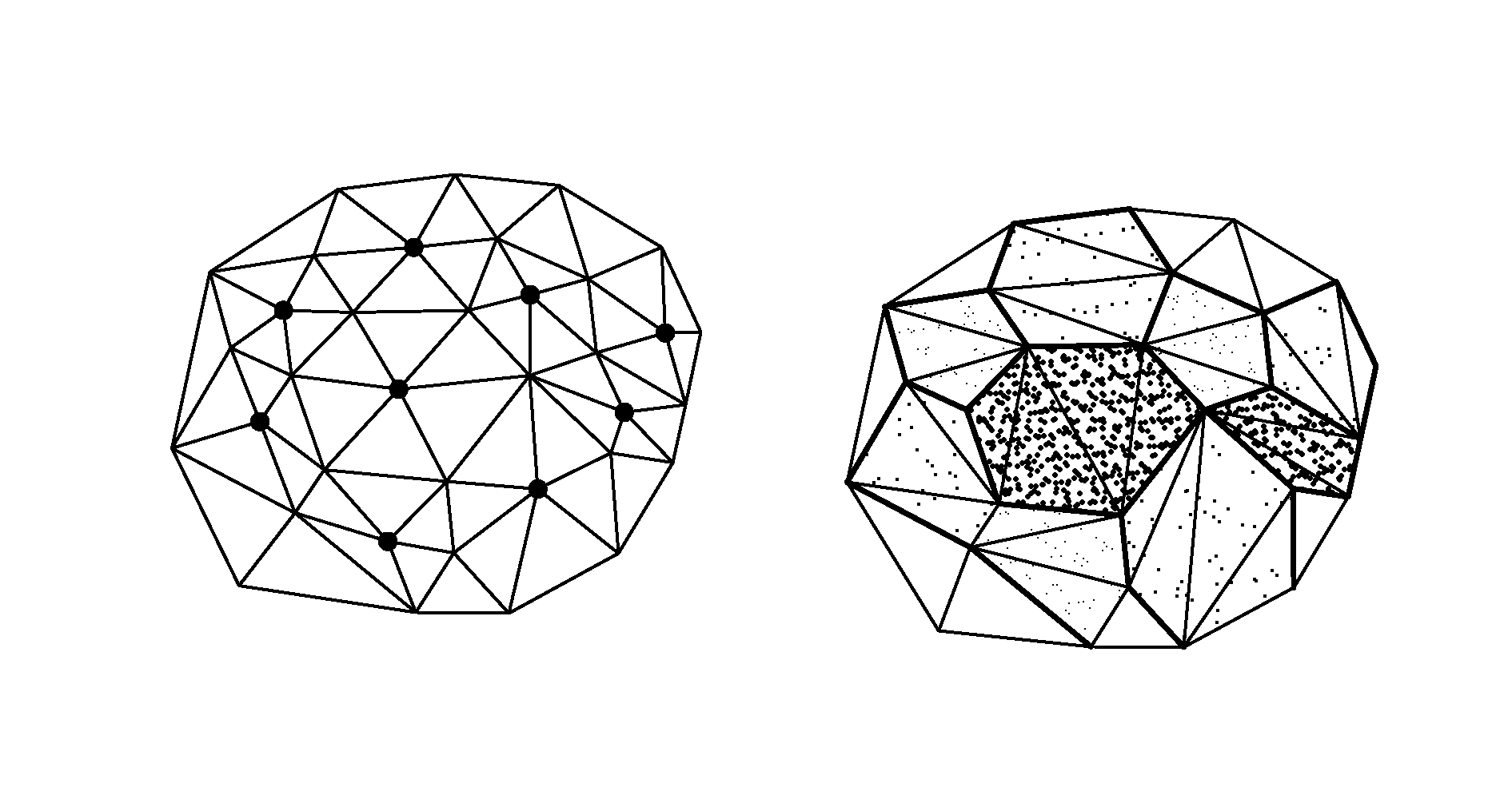
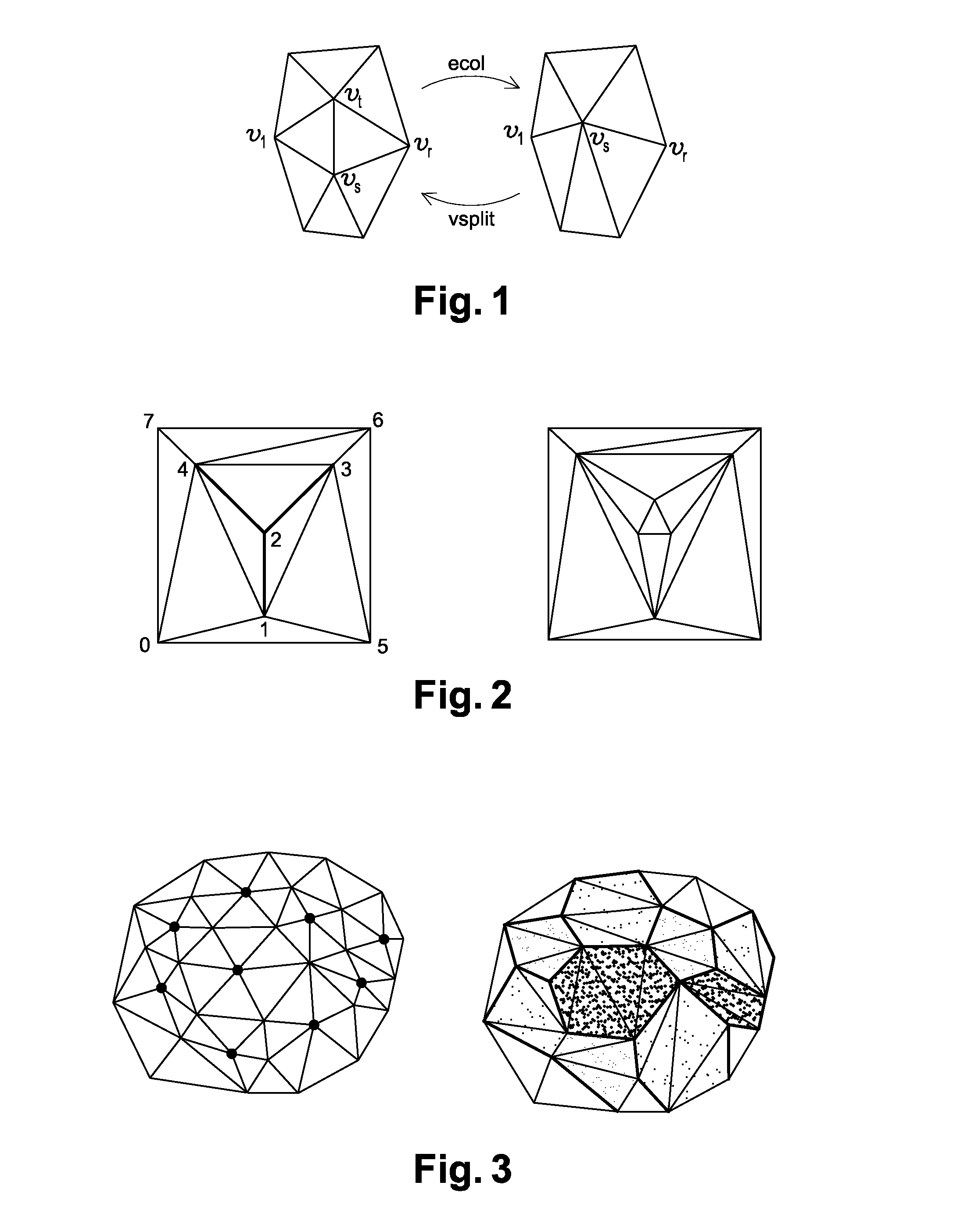
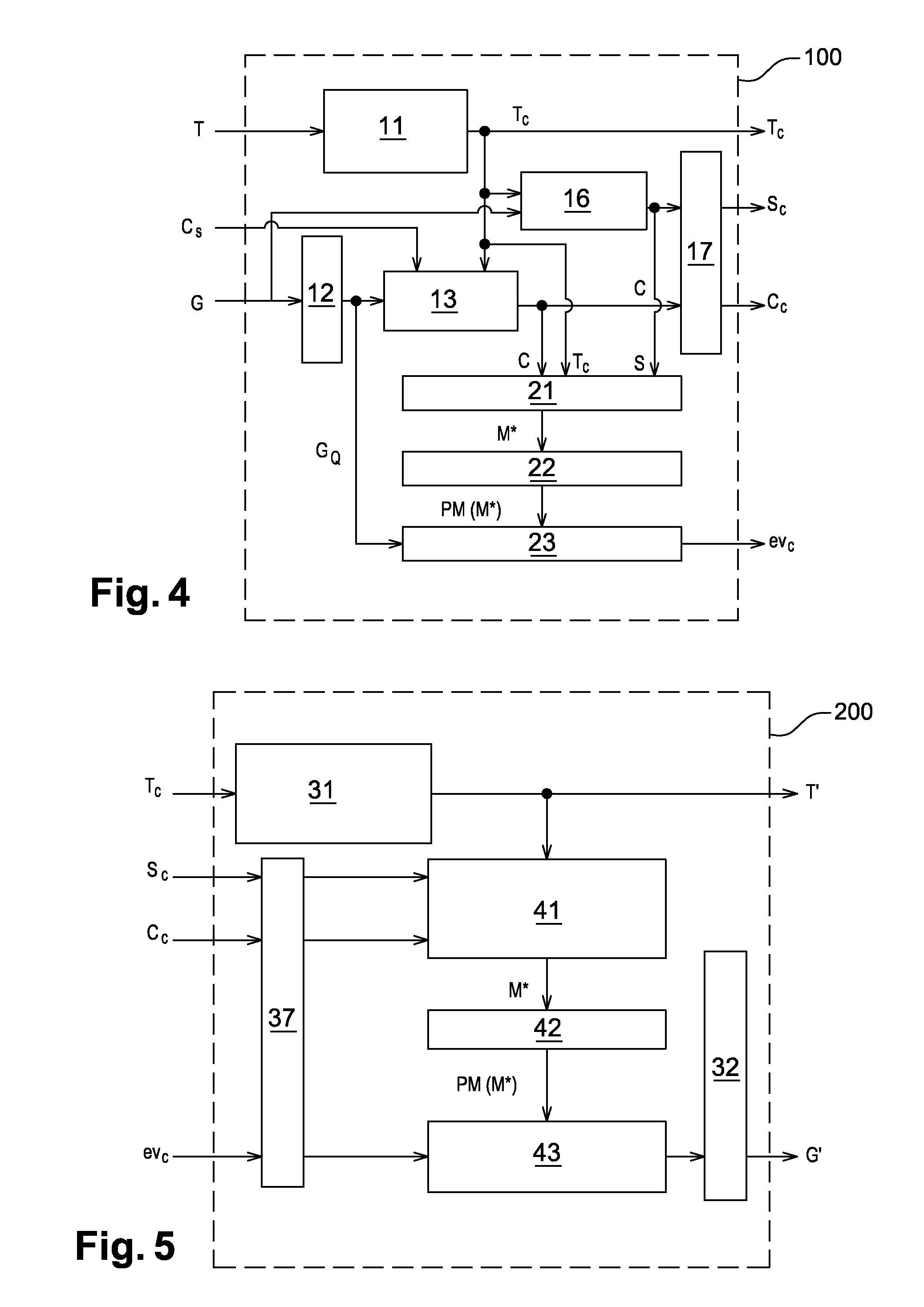
  • Method for compressing/decompressing a three-dimensional mesh
  • Method for compressing/decompressing a three-dimensional mesh
  • Method for compressing/decompressing a three-dimensional mesh

Examples


Embodiment Construction

[0022]To this end, the invention envisages in a first aspect a method for encoding / decoding three-dimensional meshes of dots or vertices connected in the form of facets delimited by edges; the mesh M is defined by connectivity data T and geometry data G;

the method comprises:

[0023]a step of lossless encoding of the connectivity data T into encoded connectivity data Tc,[0024]a step of iteratively generating a progressive mesh hierarchy, i.e. a set of meshes with progressive levels of detail, PM(M*),[0025]a step of generating a piecewise smooth approximation M* of the original mesh M, from the mesh connectivity T; this smooth approximation M* is described as follows:

[0026]a. the encoded connectivity information Tc (the list of triangles of the mesh M),

[0027]b. a small number N of control dots C=(ck)kε{1, . . . , N}, previously defined and

[0028]c. a set of indexes (their references in the mesh) S of edges, called protruding edges, of the mesh M, identified beforehand.[0029]the progressi...


PUM


Abstract

The method for encoding / decoding three-dimensional meshes of dots or vertices connected in the form of facets delimited by edges; the mesh M is defined by connectivity data T and geometry data G includes the steps of:lossless encoding of the connectivity data T into encoded connectivity data Tc,iteratively generating a progressive mesh hierarchy, i.e. a set of meshes with progressive levels of detail, PM(M*),generating a piecewise smooth approximation M* of the original mesh M, from the mesh connectivity T; this smooth approximation M* being described as follows:a. compressed connectivity data Tc;b. a small number N of control dots andc. a number of indexes S of edges called protruding edges of the mesh M, identified beforehand,using the progressive mesh hierarchy PM(M*) to calculate a prediction of approximation errors in M* compared with the original mesh M.

Description

[0001]This invention falls within the field of image processing. It relates more specifically to the image compression and decompression methods required for transmitting them and minimizing the required bandwidth.BACKGROUND OF THE INVENTION AND PROBLEM STATEMENT[0002]Over the last few years, the number of software applications using 3D images has grown exponentially: online video games, telemedicine, geographic information system, etc. The processing for these applications is made possible by the general availability of ever faster graphics processing units, as well as by the emergence of powerful 3D modeling tools and devices for directly capturing the three dimensional shapes of objects. Consequently, generated 3D content is increasingly rich and detailed.[0003]This content is generally defined by a set of dots or vertices, connected in the form of facets, which are in turn delimited by edges. Such an arrangement is known as “M mesh”.[0004]Faced with this data, whose volume incre...

Claims


Application Information

Patent Timeline
Patent Type & Authority Patents(United States)
IPC IPC(8): G06K9/36G06K9/46G06T9/00
CPCG06T9/004G06T9/001
Inventor MAMMOU, KHALEDDEHAIS, CHRISTOPHE
Owner FITTINGBOX
Learn More