
Method and system for optical microscopy

a technology of optical microscopy and optical microscopy, applied in the field of optical microscopy, can solve the problems of reducing image clarity, effectively dark or strong refracting images, and outside the focal plane, and achieve the effect of reducing drawbacks

Inactive Publication Date: 2015-07-07
MCGILL UNIV
View PDF9 Cites 1 Cited by
  • Summary
  • Abstract
  • Description
  • Claims
  • Application Information

AI Technical Summary

Benefits of technology

The present invention aims to improve optical microscopy by providing a way to capture images using both dark field illumination and fluorescence imaging simultaneously. The invention solves the problem of previous optical microscopy techniques that had limited the ability to capture images using both methods.

Problems solved by technology

Typical standard optical microscopy, bright field microscopy, suffers from limitations which include that it can only image dark or strongly refracting objects effectively, diffraction limits resolution to approximately 0.2 μm in the visible region, and out of focus light from points outside the focal plane reduce image clarity.
Optical microscopy of biological specimens, particularly live cells, is difficult as they generally lack sufficient contrast to be studied successfully; typically the internal structures of the cell are colourless and transparent.
Staining may also introduce artifacts; apparent structural details caused by the processing of the specimen and are thus not a legitimate feature of the specimen.
The disadvantage of using the dark field condenser was in necessity to limit substantially the numerical aperture (NA) of the objective to form the dark field image.
However, Vodyanoy does not address the issues identified and discussed supra in respect of the NA of the optical system nor the requirement to use fluorescent reagents.

Method used


Image

  • Method and system for optical microscopy
  • Method and system for optical microscopy
  • Method and system for optical microscopy

Examples


Embodiment Construction

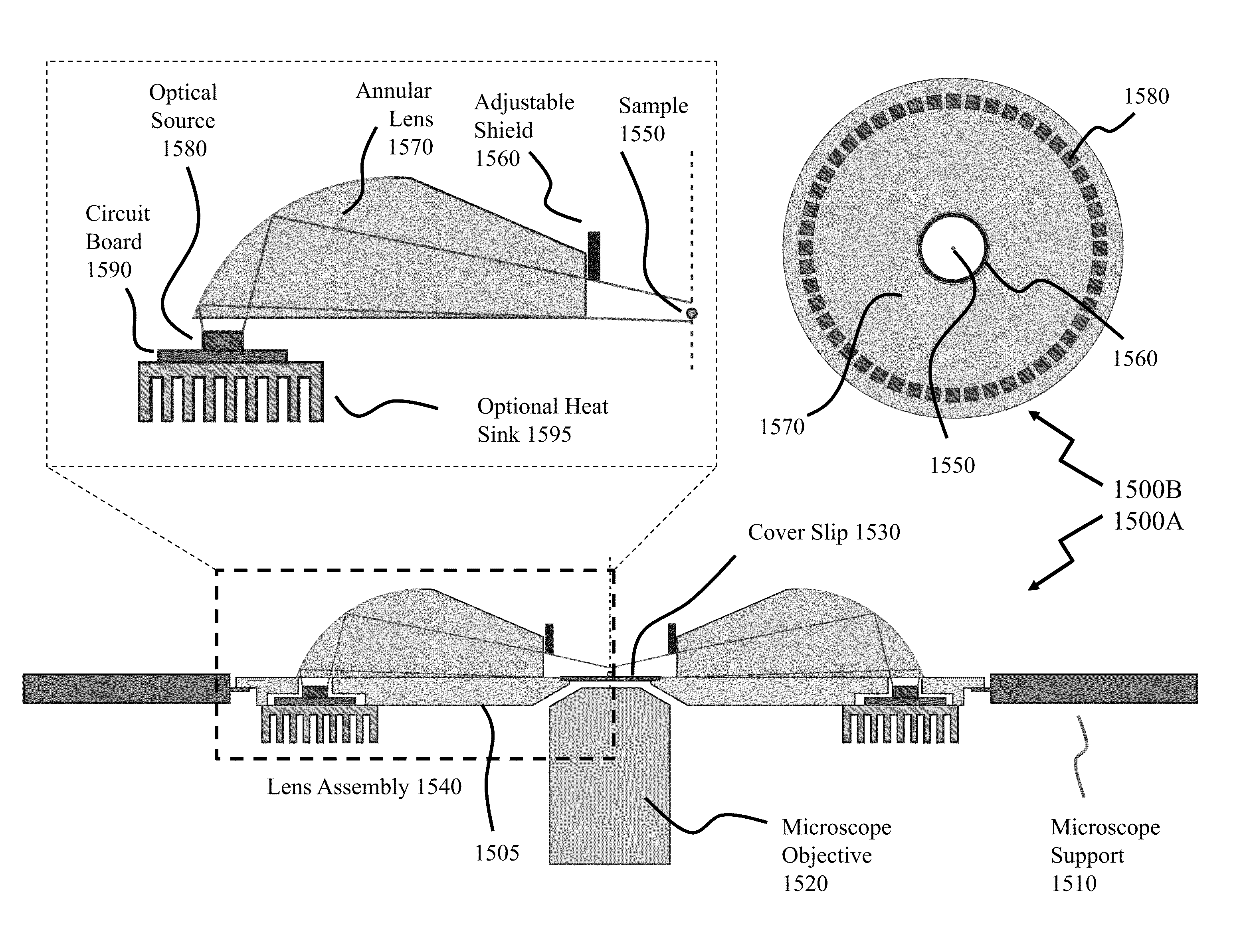
[0064]The present invention is directed to optical microscopy and more particularly to providing adjustable acceptance angle dark filed illumination in conjunction with simultaneous fluorescence imaging.

[0065]The ensuing description provides exemplary embodiment(s) only, and is not intended to limit the scope, applicability or configuration of the disclosure. Rather, the ensuing description of the exemplary embodiment(s) will provide those skilled in the art with an enabling description for implementing an exemplary embodiment. It being understood that various changes may be made in the function and arrangement of elements without departing from the spirit and scope as set forth in the appended claims.

[0066]Within microscopy a lot of attention is normally paid to what magnification and resolution of objective was employed in the image acquisition but the very important aspect of how the sample was illuminated is usually dismissed. In order to develop an imaging technique to simultan...


PUM


Abstract

Optical microscopy of biological specimens, particularly live cells, is difficult as they generally lack sufficient contrast to be studied successfully as typically the internal structures of the cell are colorless and transparent. Commonly, contrast is increased by staining the different structures with selective dyes, but this involves killing and fixing the sample. Staining may also introduce artifacts, apparent structural details caused by the processing of the specimen and are thus not a legitimate feature of the specimen. Further, microscopy of different elements of these biological specimens typically requires multiple microscopy techniques on multiple specimens. According to embodiments of the invention simultaneous imaging techniques are applied to a biological specimen such as fluorescent imaging and dark field imaging by designing an experimental evaluation system and associated illumination system addressing the conflicting demands of these approaches.

Description

FIELD OF THE INVENTION[0001]The present invention relates to optical microscopy and more particularly to providing adjustable acceptance angle dark filed illumination in conjunction with simultaneous fluorescence imaging.BACKGROUND OF THE INVENTION[0002]Optical microscopy involves passing light transmitted through or reflected from the sample through a single or multiple lenses to allow a magnified view of the sample. The resulting image can be detected directly by the eye, imaged on a photographic plate or captured digitally. The typical system of lenses and imaging equipment, along with the appropriate illumination equipment, sample stage and support, make up the optical microscope. Typical standard optical microscopy, bright field microscopy, suffers from limitations which include that it can only image dark or strongly refracting objects effectively, diffraction limits resolution to approximately 0.2 μm in the visible region, and out of focus light from points outside the focal ...

Claims


Application Information

Patent Timeline
Patent Type & Authority Patents(United States)
IPC IPC(8): G02B21/06G02B21/10G02B21/16G02B21/00
CPCG02B21/10G02B21/16G02B21/0088
Inventor RASSIER, DILSONKALGANOV, ALBERTLABUDA, ALEKSANDER
Owner MCGILL UNIV
Learn More