Manufacturing method of microstructure

a manufacturing method and microstructure technology, applied in the field of microstructure manufacturing methods, can solve the problems of inability to effectively apply the industry and the inability to accurately determine the profile of the produced microlens, and achieve the effects of enhancing the application of microstructure, increasing the number of dimensions of dragging, and increasing the complexity of the microlens to be manufactured

Active Publication Date: 2015-07-07
NAT CHENG KUNG UNIV
View PDF2 Cites 0 Cited by
  • Summary
  • Abstract
  • Description
  • Claims
  • Application Information

AI Technical Summary

Benefits of technology

[0007]In view of the foregoing subject, an objective of the invention is to provide a manufacturing method of microstructure that can produce microlens units with accurate profiles and then produce various microstructures with desired profiles by the obtained microlens units.
[0028]As mentioned above, in the manufacturing method according to the invention, different from the traditional art, the motion of a substrate relative to at least a photomask is determined in advance, such as including the angle, distance and number of times of moving and rotating, and also the profile feature of a microlens unit to be formed on the substrate is determined Then, a numerical analysis method is used to calculate and obtain the feature of the required photomask according to the determined motion of the substrate and the determined profile of the microlens unit so that the photomask can be manufactured according to the obtained feature of the photomask. After manufacturing the photomask, the substrate is driven to do the motion determined in the motion determination step, and meanwhile, a laser light is emitted to illuminate the substrate through the photomask, and then the microlens unit, i.e. expected microlens unit, will be formed on the substrate by the superposition effect of the laser light. Subsequently, by using the microlens unit with the photolithography process, the desirable microstructure can be manufactured in conformity with the requirement. Therefore, the applicability of the microstructure can be enhanced a lot.
[0029]Besides, the complexity of the microlens unit to be manufactured can be raised for the sake of the method of the invention, and therefore the microlens unit with more complexity such as an ellipse, a cone, a pyramid, a symmetric form or an asymmetric form can be manufactured. In addition, the number of dimensions of the dragging can be increased, and for example, three-time dragging can be used for getting more dimensions of the superposition effect contributed by the transparent area of the photomask. Thereby, the hexagonal close-packed microlens array can be manufactured, allowing the filling rate of the structure to be increased. The crucial point of the invention is, the microlens unit with the pre-designed profile can be accurately manufactured, thereby bringing enormous economic value and applicability.

Problems solved by technology

However, since the photomask pattern is defined by quadratic curves and only the orthogonal two-dimensional dragging is used in the process, the profile of the produced microlens can not be accurately determined.
Hence, such inaccurate microlens structure produced by the laser dragging process that has not been optimized can not fit the desired profile, thus unable to be effectively applied to the industry.

Method used


Image

  • Manufacturing method of microstructure
  • Manufacturing method of microstructure
  • Manufacturing method of microstructure

Examples


Embodiment Construction

[0038]The present invention will be apparent from the following detailed description, which proceeds with reference to the accompanying drawings, wherein the same references relate to the same elements.

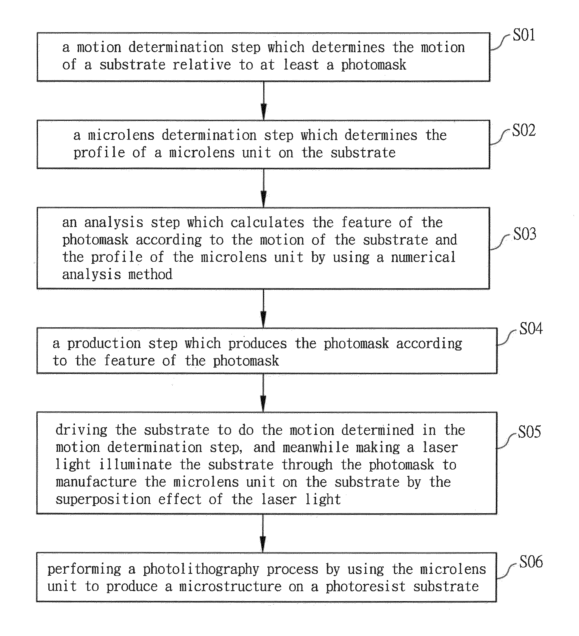
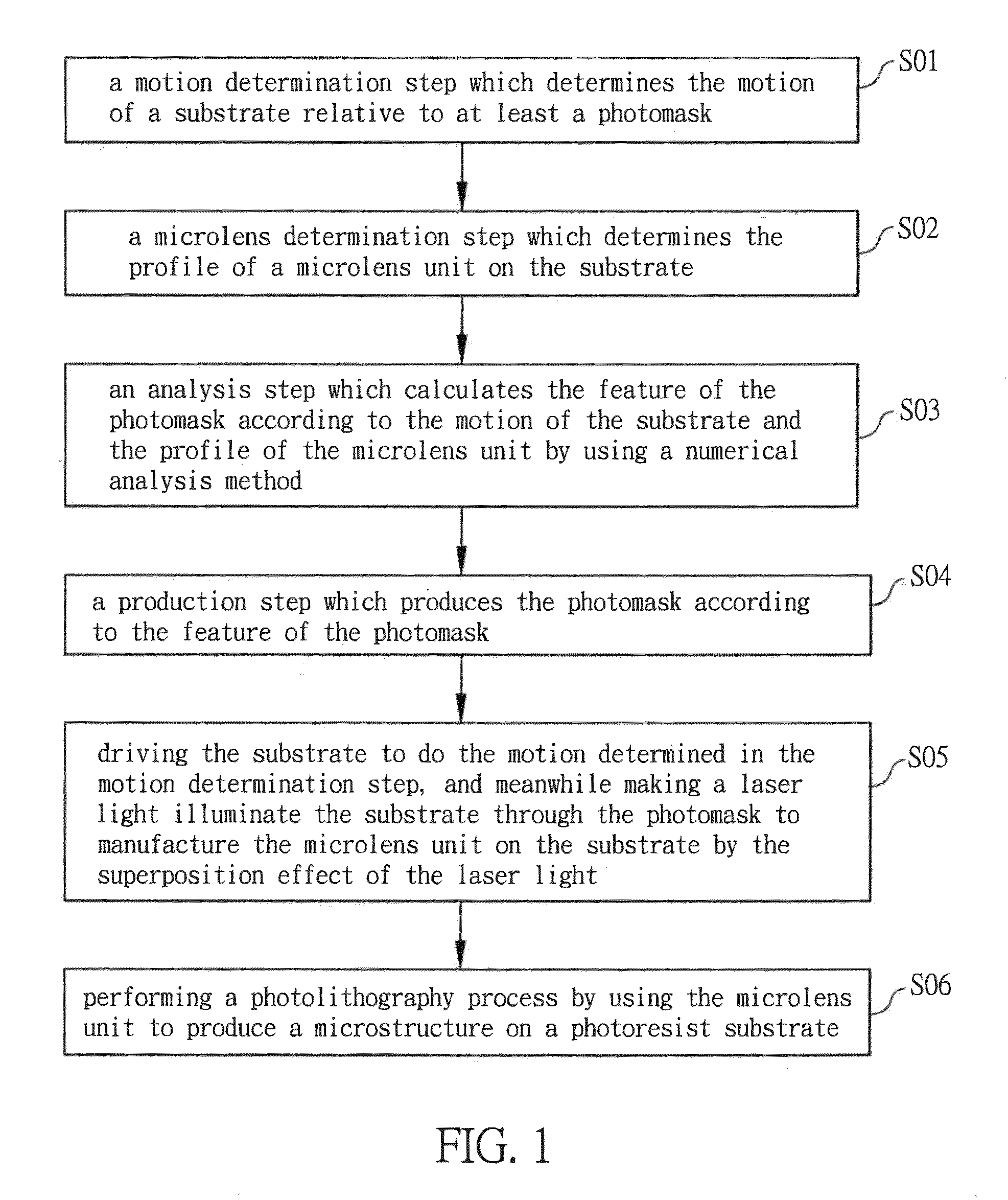
[0039]FIG. 1 is a flow chart of a manufacturing method of microstructure according to a preferred embodiment of the invention. The manufacturing method of microstructure of this embodiment can be mainly divided into two parts, the first part concerning the manufacturing of the photomask and the microlens unit and the second part concerning the microstructure manufactured by using the microlens unit. The first part is described as below first.

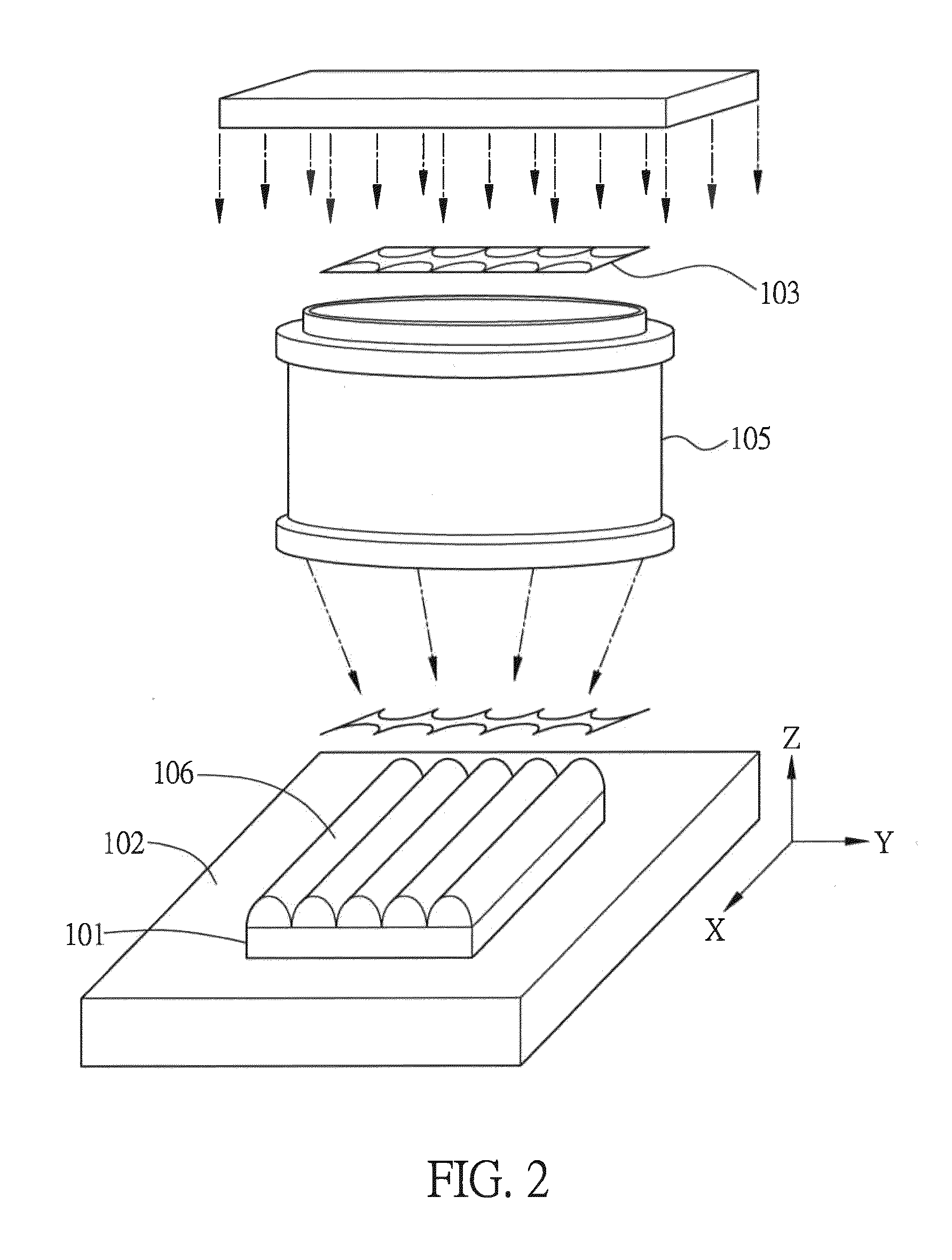
[0040]In this embodiment, the photomask and the micro lens unit are manufactured by the laser dragging process (LDP). FIG. 2 is a schematic diagram showing the manufacturing of the photomask and the microlens unit. The laser dragging process is briefly introduced first hereinafter. The laser dragging process uses the photomask projection method co...


PUM

PropertyMeasurementUnit
sizeaaaaaaaaaa
microstructureaaaaaaaaaa
angleaaaaaaaaaa

Abstract

A manufacturing method of microstructure comprises steps of: a motion determination step which determines the motion of a substrate relative to at least a photomask; a microlens determination step which determines the profile of a microlens unit on the substrate; an analysis step which calculates the feature of the photomask according to the motion of the substrate and the profile of the microlens unit by using a numerical analysis method; a production step which produces the photomask according to the feature of the photomask; driving the substrate to do the motion determined in the motion determination step, and meanwhile making a laser light illuminate the substrate through the photomask to manufacture the microlens unit on the substrate by the superposition effect of the laser light; and performing a photolithography process by using the microlens unit to produce a microstructure on a photoresist substrate.

Description

BACKGROUND OF THE INVENTION[0001]1. Field of Invention[0002]The invention relates to a manufacturing method of microstructure and, in particular, to a manufacturing method of microstructure wherein the microstructure is produced by focal light spots through a microlens unit.[0003]2. Related Art[0004]The laser dragging process uses the photomask projection method cooperated with a precise displacement platform to allow the pattern on the photomask to be superposed on a surface of a substrate in different directions and depths so as to produce various 3D microstructures rapidly and largely. Because the profile of the microstructure is totally determined by the transparent pattern of the photomask, the design of the photomask is the most crucial of all parts for the laser dragging process.[0005]The laser dragging process is most frequently used for producing a microlens array. However, since the photomask pattern is defined by quadratic curves and only the orthogonal two-dimensional dr...

Claims


Application Information

Patent Timeline
Patent Type & Authority Patents(United States)
IPC IPC(8): G06F17/50G03F7/20
CPCG03F7/20G03F7/70425G03F7/70733
Inventor LEE, YUNG-CHUNCHIU, CHI-CHENGCHANG, CHIH-HAOLU, CHING-YUN
Owner NAT CHENG KUNG UNIV
Why Eureka
Try Eureka