Multiple direct touring positions for snowboard boot binding mounting base

a technology mounting bases, which is applied in the direction of ski bindings, skis, sport apparatus, etc., can solve the problems of affecting the use occupying too much space, and reducing the usefulness of snowboard boot bindings, so as to facilitate locking and unlocking, increase the usefulness, and increase the weight and manufacturing

Inactive Publication Date: 2015-07-14
EKBERG LANE A
View PDF53 Cites 7 Cited by
  • Summary
  • Abstract
  • Description
  • Claims
  • Application Information

AI Technical Summary

Benefits of technology

[0016]The prior art concepts for a soft shelled boot touring binding system particularly for snowboard boots all utilize designs that the user must use a separate snowboard binding base adaptor piece with holes oriented for attaching snowboard binding base and 3-4 hole disk to be mounted by bolt or screw to the separate mounting plate adaptor. The said adaptor includes a touring pivot in the toe region and secondary locking points in the adaptor to stop the walking tour pivot especially when in a snowboard mode thus created more weight and manufacturing than is necessary. Typical split-board bindings in the prior art utilize such bindings, adaptors, and interfaces. The present invention overcomes the prior art by providing a snowboard boot mounting plate or base with a quick release detachable walking mode which includes a detachable touring axle pivot pin axis directly to the mounting base binding and device ski interface and a secondary lock position also located on the boot mounting plate or boot base which is a locked heel position for a fixed slide mode on a ski touring device meaning the boot binding cannot pivot while coupled to the ski shaped device. In one embodiment of the present invention the heel is locked in a fixed or non-touring mode for sliding on a ski shaped device like a snowboard, split ski / board, or touring ski by a locking mechanism connected to the ski shaped device that engages the underside of the boot mounting plate by a locking movement or mechanism or pin that runs parallel with the a longitudinal direction on the boot mounting plate or the direction the footwear or snowboard boot points and on the same boot mounting plate the touring pivot axle can engaged in a transverse position in the boot mounting plate and touring ski. In a separate embodiment the heel lock may also run locking movements or fixed mechanisms parallel with the touring locking motion. Thus the prior art is overcome by combining the climb and glide adaptor with a boot binding plate or base into one manufactured piece eliminating the adaptors / screws and increasing usefulness and a plurality of locking points across the boot mounting plate.
[0017]In one embodiment the axle pivot pin used for the touring mode on the mounting plate as well as a locking tool reward the touring pivot dock on the mounting plate has quick-release and quick-attaching features allowing it to change position in a quick easy manner from the touring mode to other modes within the mounting plate. The axle pivot pin may have, in a separate embodiment, connective features on the axle to hold axle permanently or non permanently in the boot base plate to facilitate locking and unlocking the axle pivot pin axis or axes from any locked mode or travel mode position interface. Exampled features disclosed herein are a cotter pin and c-clamp though a multitude of systems could be used within the spirit of the invention. The cotter pin offering a quick-release option for the axle pivot pin. It must be noted that a multitude of options exist to secure both ends of the axle by features present on both ends of the axle which prevent the axle from sliding one way or another from its locked position due to features on at least one side of the axle pivot pin that secure it. In a separate embodiment at least one feature on one side of the axle or axle dock may be released or moved to allow the axle pivot pin releasing movement from its docked position on another interface. In another embodiment the axle pivot pin has been made longer then axles pivot pins and clevis pins in the prior art to create a longer span of strength for the rider of the climbing sliding device. In one embodiment the axle pivot pin ends extend beyond the periphery of the devices it selectively mounts to. In another embodiment the axle has been made shorter but is oriented in dimensions that have suitable strength to facilitate the utility of this named invention. It is obvious that a multitude of metals could be used or other materials, bends, axle structures, axle positions, to construct the axle pin to work in accordance with the present invention.
[0018]The boot mounting plate design in one embodiment consists of a boot bed for which the boot sits directly on, two flanges in the foot bed for resilient straps to be mounted to connect a boot to the top plane of the foot bed. In further flange embodiments the flange could be bolted, screwed, welded, or riveted and the like to the boot base plate. In one embodiment the axle pivot pin locking / docking areas are located adjacent the sole “plane” of the mounted boot with in at least two ribs, walls, spring loaded latch, latch, or rail structures and the like which support the axle pivot pin in a locked state in an interface and the boot mounting plate. In separate embodiments portions of at least one of a wall, rib, flange, or rail extend from the boot mounting plate foot bed. The boot mounting plate has pivot pin locking areas in the toe region of the boot mounting plate for the walking tour mode and secondary locking areas and structures rearward the toe pivot for a locked heel mode or a snowshoe pivotal mode, or even a secondary telemark binding plate touring position. The axle pivot pin generally is in a transverse position on the riding device interface and boot mounting plate when inserted in both and locked to interfaces of the split-ski / board, ski, board, snowshoe, hybrid, binding plate interface. In a further embodiment the boot mounting base has material removed creating a window or aperture. This material could be from the boot bed area or adjacent the boot bed area to form the window. In further embodiments there could be a series of windows, ribs, beams, window shapes, in the boot bed. This is advantageous to reduce weight, create boot bed structures, add locking points or structures, or add simple weight reducing aesthetics. In an embodiment only one lock feature is used to couple the boot mounting base in the locked heel mode for down hill sliding on the ski touring device. In a further embodiment the one lock feature is reward the touring lock feature wherein the touring lock feature is left unlocked while a different lock feature reward the touring lock feature is locked.
[0019]The boot mounting base plate in one embodiment has at least three separate lock points regions provided across the boot mounting plate with at least two selectively providing a locked heel sliding mode. In further embodiments the touring mode position can remain in a the first touring position axle axis with the boot mounting plate able to selectively use a secondary lock interface to form lock heel mode without having to move the boot mounting plate out of touring mode. In a further embodiment at least one lock region comprises two lock features to facilitate locking the one region. The first interface region is a touring mode interface, the second interface region is a touring mode or lock heel mode interface region reward the touring mode region towards the mid plate, and the third interface region is reward the mid region of the boot mounting plate. The locking points could be moved to facilitate other designs without leaving the spirit of a three interface region boot mounting plate in one embodiment or more embodiments of the present invention.

Problems solved by technology

In the current state of the art, boot mounting plates for touring skis, touring snowboards, and split-ski / boards are all limited by cumbersome binding systems which have complex hardware, a multitude of parts, adaptors, and adaptor interfaces that take up space, weight, money, and time.
Furthermore, the current state of the art does not provide a snowboard boot binding that has material removed to reduce the weight of the mounting plate and make the boot sole visible through a window in the mounting plate.
All current touring ski systems and touring snowboard systems have a complex binding set-up that is heavy and most importantly takes up too much space and is too expensive.
There also lacks a snowboard boot binding system that can allow selective touring ski pivots wherein the adaptor is part of the device binding as one unit and universally accepted on a ski, snowshoe, split-ski / board combination type devices and the like.
However, some touring snowboard bindings have a “short” quick-release touring axle which releases an adaptor plate.
However, it must be noted that the prior art of soft shelled boot touring has not produced a mounting plate that includes front and rear strap portions connected directly to the mounting plate unit for retaining soft shelled boots when touring including a releasable touring axle pivot pin for multiple travel modes in and out of the binding directly.
Additionally the prior art snowboard boot touring bindings have not produced a mounting plate interface that the snowboard boot can be mounted directly on.
Furthermore, prior art snowboard boot bindings have not produced a boot bed with a boot sole window allowing the boot bottom to be visible through the boot bed when the boot is mounted to the boot bed.

Method used


Image

  • Multiple direct touring positions for snowboard boot binding mounting base
  • Multiple direct touring positions for snowboard boot binding mounting base
  • Multiple direct touring positions for snowboard boot binding mounting base

Examples


Embodiment Construction

[0069]Reference throughout this specification to “one embodiment,”“an embodiment,” or similar language means that a particular feature, structure, or characteristic described in connection with the embodiment is included in at least one embodiment of the present invention. Thus, appearances of phrases “in one embodiment,”“in an embodiment,” and similar language throughout this specification may, but do not necessarily, all refer to the same embodiment.

[0070]Furthermore, the described features, structures, or characteristics, of the invention may be combined in any suitable manner in one or more embodiments. One skilled in the art will recognize, however, that the invention can be practiced without one or more of the specific details, or with other methods components, materials, and so forth. In other instances, well known structures, materials, or operations are not shown or describe in detail to avoid obscuring aspects of the invention.

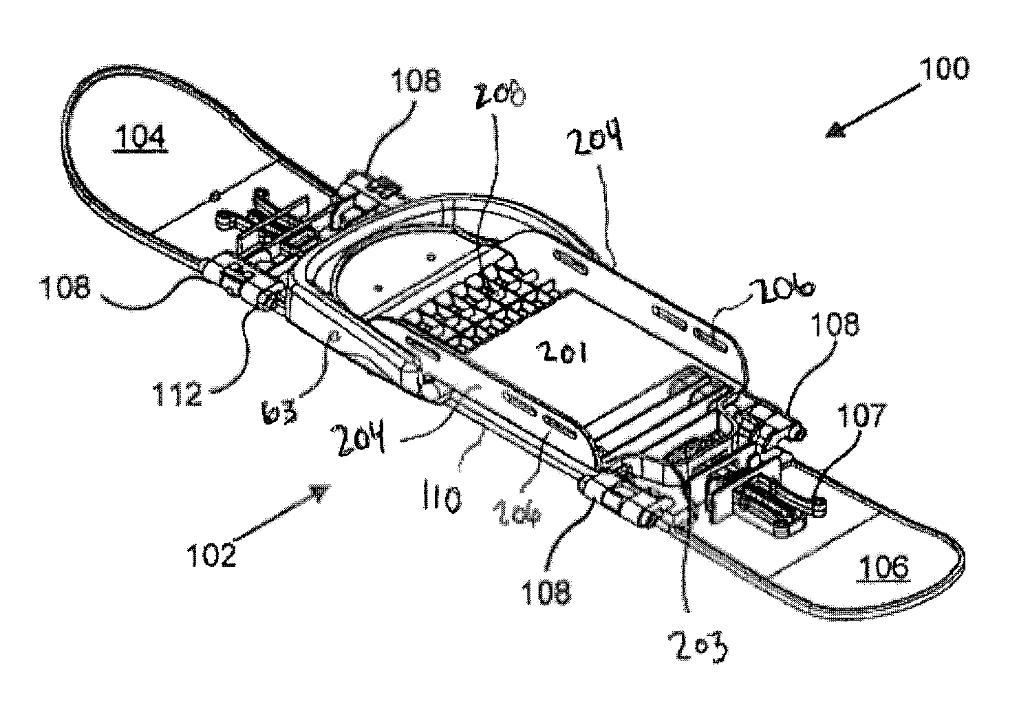
[0071]FIG. 1 is a top perspective view of a mo...


PUM


Abstract

A binding device for a snowboard boot to rest upon to secure user to a climb and slide device in selective modes including a split ski climbing mode and an attached ski section sliding mode, for traversing mainly over snow and ice covered terrain. A binding device includes a mounting base including multiple direct locking features in the mounting base with which to interact with mating interfaces on a ski shaped touring device binding interfaces. An axle pivot pin axis system is also disclosed that may selectively articulate the mounting plate in a walking motion on the ski touring device. A selective locked heel mode with locking ability directly on the mounting plate is disclosed. A first position wherein the boot mounting base may articulate in a walking motion on an axle pivot pin axis when connected to a ski touring device and a second position wherein the walking motion of the mounting base is prevented while connected to the ski touring device and a third position wherein the mounting base is not coupled to a ski device during mode transition.

Description

CROSS-REFERENCES TO RELATED APPLICATIONS[0001]This application is a continuation in part and claims benefit of U.S. patent application Ser. No. 12 / 716,136 entitled “MULTIPLE DIRECT LOCK POSITIONS FOR TOURING SKI MOUNTING PLATE” and filed on Mar. 2, 2010 which claimed priority to U.S. patent application Ser. No. 11 / 247,893 entitled “CONFIGURABLE SNOWSHOE AND SKI DEVICE” and filed on Oct. 7, 2005, for Lane Ekberg, which is incorporated herein by reference.BACKGROUND[0002]This invention relates to the field of devices that traverse over snow, ice, and colder climates of the earth in a climbing or sliding fashion. Namely, boot retention devices otherwise known in the field as boot bindings, binding plates, mounting plates, mounting bases, snowboard boot bindings, touring ski bindings, soft shelled boot bindings, approach ski bindings, and the like and especially those meant for selective free heel touring and lock heel sliding positions for ski shaped touring devices. This invention als...

Claims


Application Information

Patent Timeline
Patent Type & Authority Patents(United States)
IPC IPC(8): A63C5/00A63C13/00A63C9/00A63C5/02
CPCA63C9/00A63C5/02A63C13/003A63C13/005A63C13/006A63C2203/06A63C9/06
Inventor EKBERG, LANE A.
Owner EKBERG LANE A
Why Eureka
Try Eureka