
Dual purpose screw coupling piece

a screw coupling and screw technology, applied in the field of dual-purpose screw coupling pieces, can solve problems such as unintentional leakage of compound, problems that may also present themselves, and suboptimal performance, and achieve the effects of less intensive, avoiding difficulties and safety issues, and avoiding or reducing problems

Active Publication Date: 2015-07-14
SOUDAL
View PDF7 Cites 7 Cited by
  • Summary
  • Abstract
  • Description
  • Claims
  • Application Information

AI Technical Summary

Benefits of technology

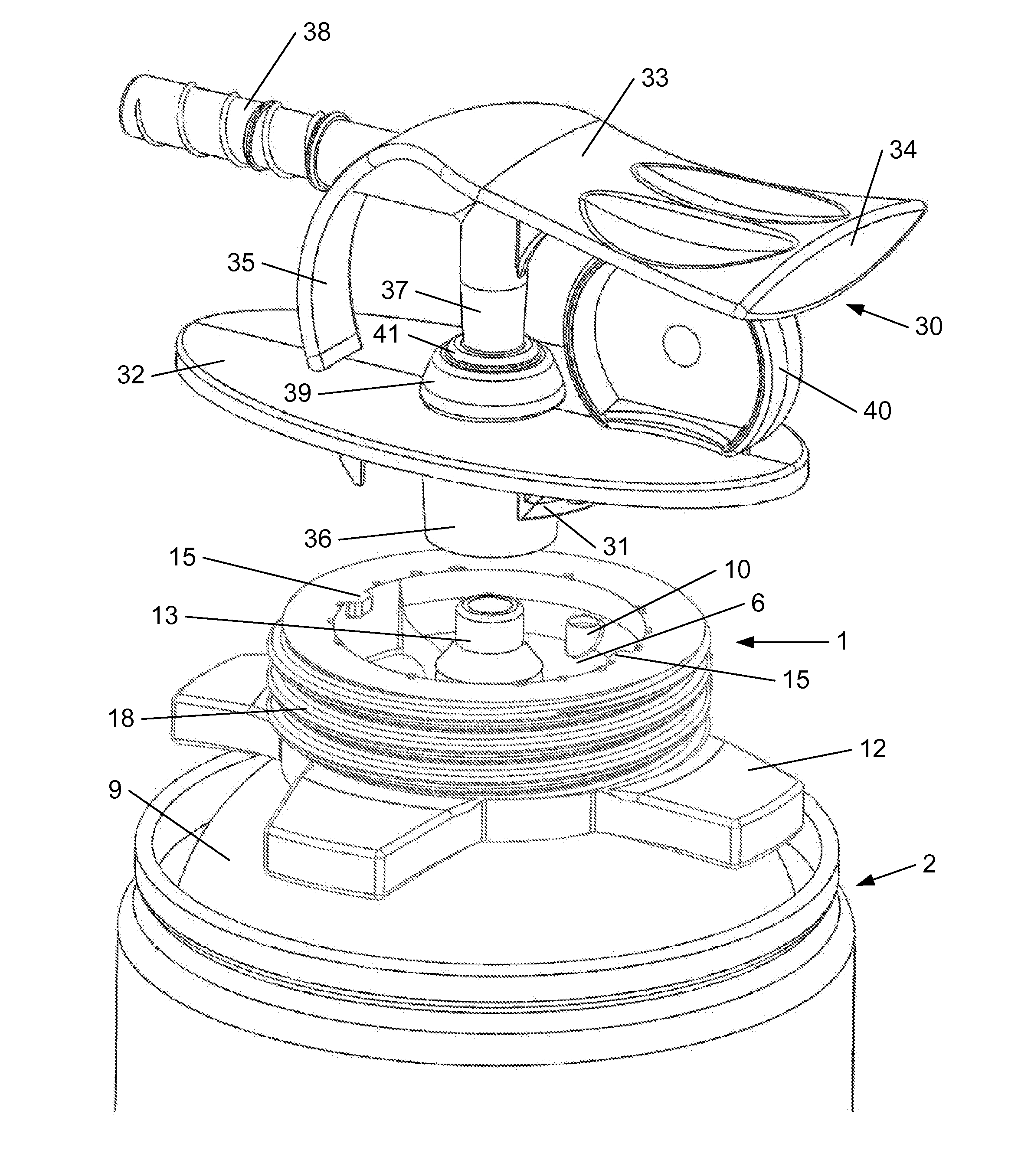
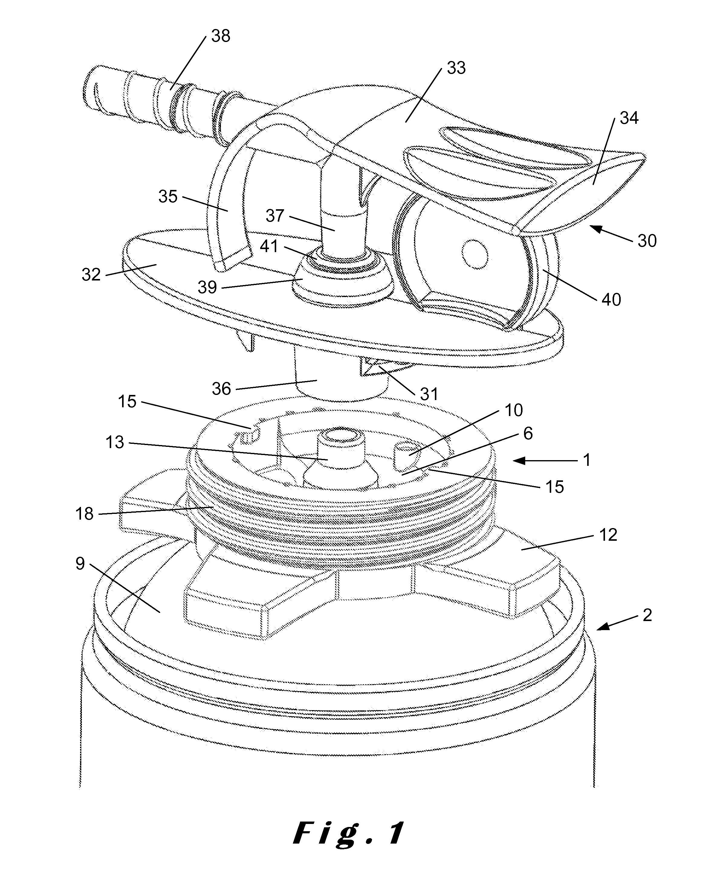
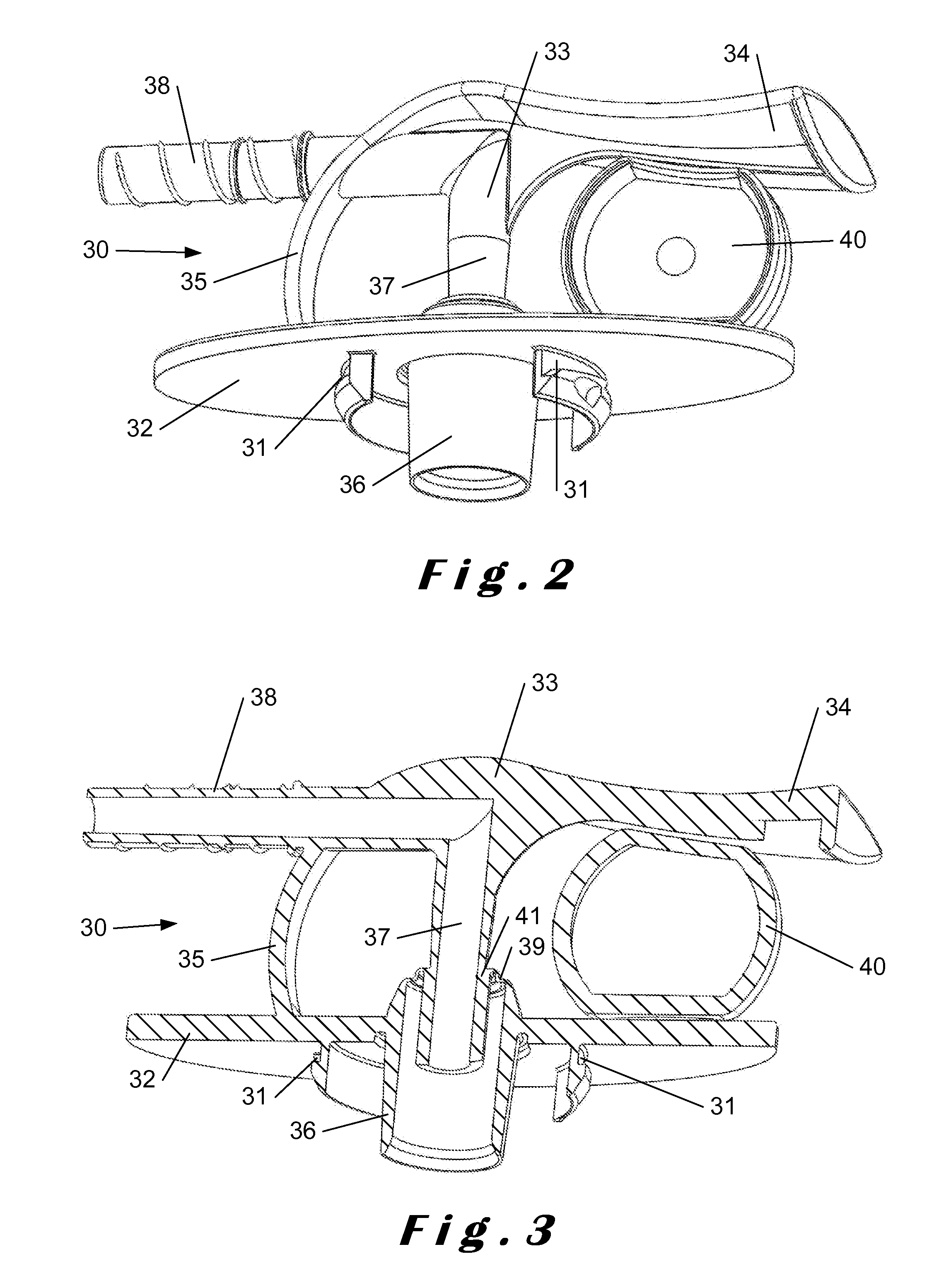
[0025]The coupling piece according to the invention provides the advantage that the coupling piece is dual purpose, i.e. it may be used in combination with an application device or a dispensing gun, optionally by means of a second coupling piece, such as for intensive use by e.g. a professional or intensive DIY user or for smaller crevices, cavities or cracks, but it is at the same time also suitable for use of the container to which it is attached in handheld mode, with a suitable handheld applicator, such as for less intensive use or for larger crevices, cavities or cracks. This brings the significant advantage that the supply chain only needs to carry one type of products, i.e. the assembly of a full container with the coupling piece according to this invention, in order to satisfy the needs of the two uses or type of users. It also avoids the difficulties and safety issues associated with removing the coupling piece from the container before one of the known handheld applicators can be snapped onto the flange around the valve cup of the container. The applicants have found, as explained above, that the valve cup may become bulged by the internal pressure, and temperature, building up in the container after filling and closing, possibly after homogenising its content for starting the chemical reaction. This may thus lead to a mismatch between the container valve stem location and the dispenser device or gun applicator, and may thus lead to suboptimal performance, such as unintentional leakage of compound when the container is coupled to the gun applicator. The applicants have found that this problem may also present itself when a handheld applicator is coupled with the coupling piece already attached to a container. This coupling operation may thus also lead to unintentional leakage of compound when the handheld applicator is coupled to the assembly, which may present several problems to the user, including a safety risk.
[0026]The applicants have found that these problems with the screw coupling may also be alleviated by the coupling piece according to the present invention. The first coupling piece according to the present invention therefore comprises the internal support rim or the one or more internal support legs which are providing an internal rim or sections of an internal rim for engaging with the outer surface of the valve cup of the container valve for when the first coupling piece is attached to the container. This provides exterior support for the valve cup such that the valve stem is maintained in its original position even when the pressure increases inside the container. This thus avoids or mitigates the problem of valve stem repositioning which is explained above. Also the risk for premature leakage of compound during the effectuation of the coupling with the dispensing gun or with the handheld applicator is reduced, as well as the risk for other flaws in the operation of the assembly.
[0030]The advantage of this handheld applicator is that, together with the matching coupling piece, it provides for the possibility to use the container provided with the coupling piece suitable for professional use with a dispensing gun also in handheld mode. This allows the supply chain to offer only one product for the two uses or type of users.

Problems solved by technology

This may thus lead to a mismatch between the container valve stem location and the dispenser device or gun applicator, and may thus lead to suboptimal performance, such as unintentional leakage of compound when the container is coupled to the gun applicator.
The applicants have found that this problem may also present itself when a handheld applicator is coupled with the coupling piece already attached to a container.
This coupling operation may thus also lead to unintentional leakage of compound when the handheld applicator is coupled to the assembly, which may present several problems to the user, including a safety risk.

Method used


Image

  • Dual purpose screw coupling piece
  • Dual purpose screw coupling piece
  • Dual purpose screw coupling piece

Examples


Embodiment Construction

[0044]The containers for compounds under pressure are typically designed as cylinders. The bottom is usually closed off by flanging a concave bottom plate onto the cylinder. The top of the cylinder is typically closed off by flanging on a convex head plate, with therein a central opening through which the container may be filled with its content. As explained before, after filling, this opening may be closed off with a valve through which the container content may be released using the pressure which is built up inside the container. At room temperature, the pressure inside a filled and ready-to-use container is typically about 5 bar gauge. The containers are typically able to remain intact up to a pressure of 18 bar gauge, and are designed to not burst open with a pressure below 21.6 bar gauge. The valve is typically designed to resist a pressure up to at least 22 bar gauge. Other containers exist, which are only able to remain intact up to a pressure of 12 or 15 bar gauge. The con...


PUM


Abstract

A dual purpose coupling piece is provided for on the one hand the screw coupling of a disposable pressure container with a dispensing gun, and which further includes means for on the other hand also cooperating in a bayonet-type coupling with a suitable handheld applicator for application of the compound as in the handheld use. A suitable handheld applicator is also provided. The coupling piece and / or the handheld applicator may be designed for the production as one single product using injection moulding. Further provided is an assembly of a container with the coupling piece, and a process for producing the coupling piece and the assembly, as well as the handheld applicator.

Description

CROSS-REFERENCE TO RELATED APPLICATIONS[0001]This application is the entry into the United States of PCT Application Number PCT / EP2011 / 058858 filed May 30, 2011 and claims priority from European Patent Application Number EP / 10164924.2 filed Jun. 4, 2010, the entirety of each of which are hereby incorporated by reference.FIELD OF THE INVENTION[0002]The current invention relates to containers, cans or canisters containing a compound under pressure, in particular disposable containers, and which can be coupled to a device, typically called a dispensing gun, for applying the compound. The compound is usually reactive or curable, may thus comprise one or more active components, and may be suitable to form for example a sealant (e.g. a silicone paste), a polyurethane (PU) foam, or a two component glue. The invention is particularly concerned with improvements in the pieces forming the coupling between the container and the dispensing gun or of the container with a handheld applicator.BACK...

Claims


Application Information

Patent Timeline
Patent Type & Authority Patents(United States)
IPC IPC(8): B65D83/00B65B1/04B65D83/20B65D83/22B65D83/46B65D83/38B65D83/30B05B9/08
CPCB65B1/04B65D83/201B65D83/226B65D83/46B05B9/0805B65D83/202B65D83/303B65D83/38
Inventor VERVOORT, BARTGEBOIS, PETERHERMANS, MARCFAZEKAS, GABOR
Owner SOUDAL
Learn More