
Light fixture assembly

a technology of light fixture and assembly, which is applied in the direction of fixed installation, light source semiconductor devices, lighting and heating apparatus, etc., can solve the problems of reducing the operable life of many reducing reliability and operational life, and reducing the reliability of led based illumination assemblies. , to achieve the effect of reducing the voltage delivered, reducing the voltage, and reducing the voltag

Inactive Publication Date: 2015-07-14
SODERMAN DARYL +1
View PDF105 Cites 29 Cited by
  • Summary
  • Abstract
  • Description
  • Claims
  • Application Information

AI Technical Summary

Benefits of technology

This patent is about a light fixture assembly that is designed to dissipate excessive heat generated from LED arrays. The fixture uses normal structural components to transfer heat from the LEDs to the surrounding environment, ensuring optimal efficiency and a long life. One embodiment of the fixture also uses Power over Ethernet (PoE) cable to provide both data connection and electrical power to the fixture. This allows for long cable lengths and the use of spare wire conductors for powering electrical devices. Overall, the patent focuses on improving the heat-dissipating capabilities of LED light fixtures and utilizing PoE cable for powering and data transfer.

Problems solved by technology

However, certain disadvantages and problems associated with the use of LED based illumination assemblies are commonly recognized.
As such, LED illumination assemblies tend to generate a significant amount of heat during their operation, which in turn may derogatorily affect the light generated by the LED array as well as reduce the reliability and operational life thereof.
Accordingly, the operable life of many LED based illumination assemblies may be significantly reduced due to premature failure of one or more light emitting diodes associated with a light fixture or other device, and / or the maximization of power and illuminating output for such an illumination assembly is limited.
However, many known attempts do not effectively accomplish optimal heat transfer, resulting in lower operational performance and a reduced operational life as generally set forth above.
Moreover, there is especially a need as it relates to recessed or flush lighting wherein traditional heat dissipating structures are hampered by being contained within a wall or other mounting surface.
Specifically, known recessed or flush mounting structure typically include large unattractive heat sinks contained within the mounting surface and / or otherwise concealed.
Even then, however, there are limitations on the power and illumination ability of the light source, as there are usually space and weight constraints for the recessed heat sink, especially in the context of a retrofit wherein the cavity into which the light source will be positioned has been predefined based upon conventional incandescent lighting specifications.

Method used


Image

  • Light fixture assembly
  • Light fixture assembly
  • Light fixture assembly

Examples


Embodiment Construction

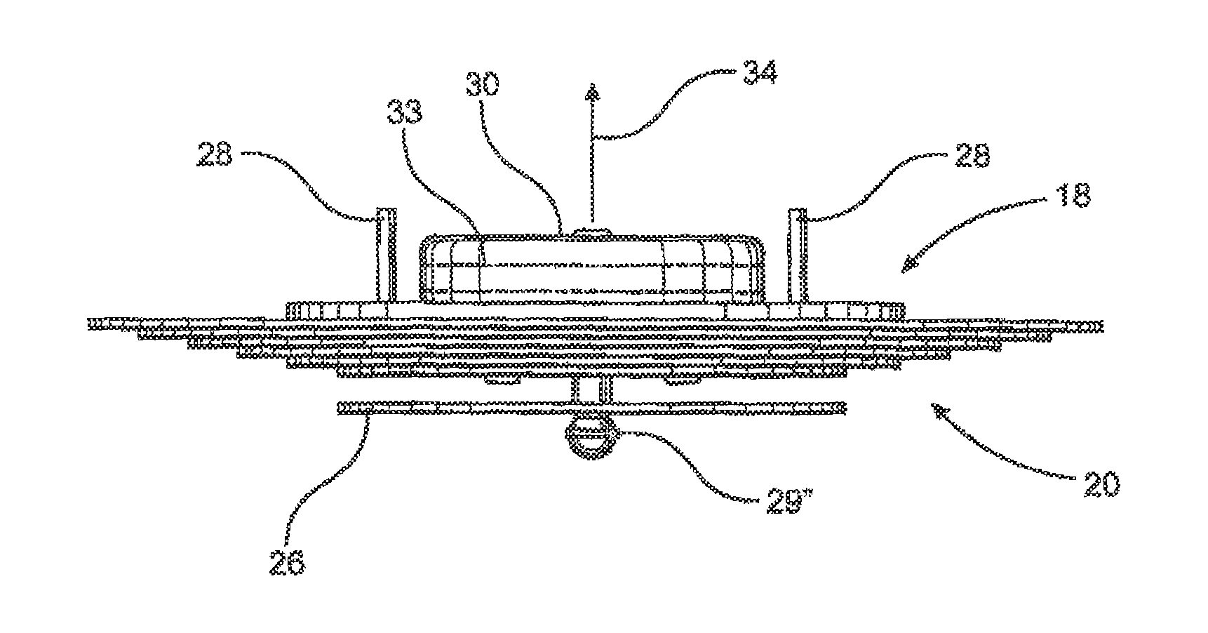
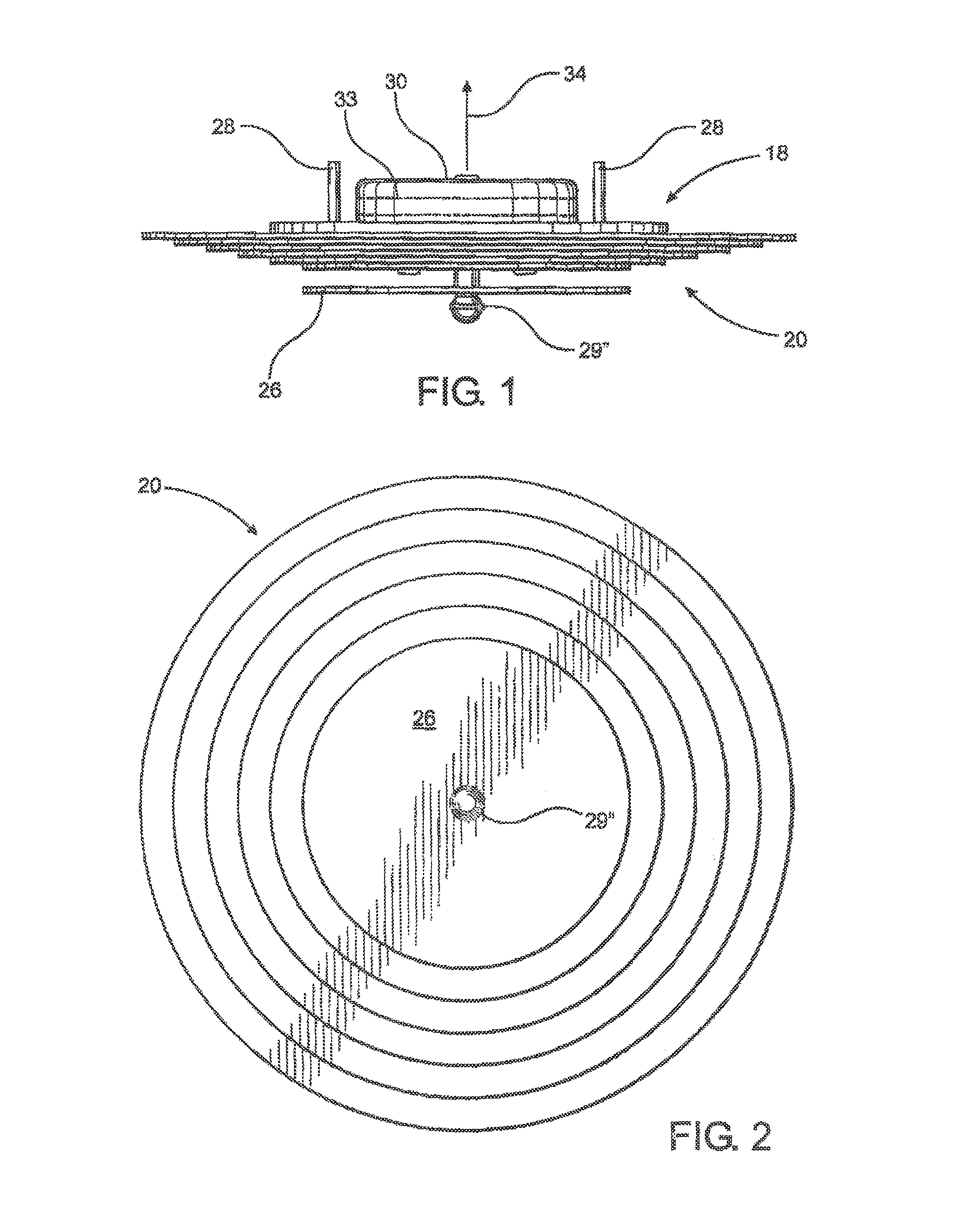
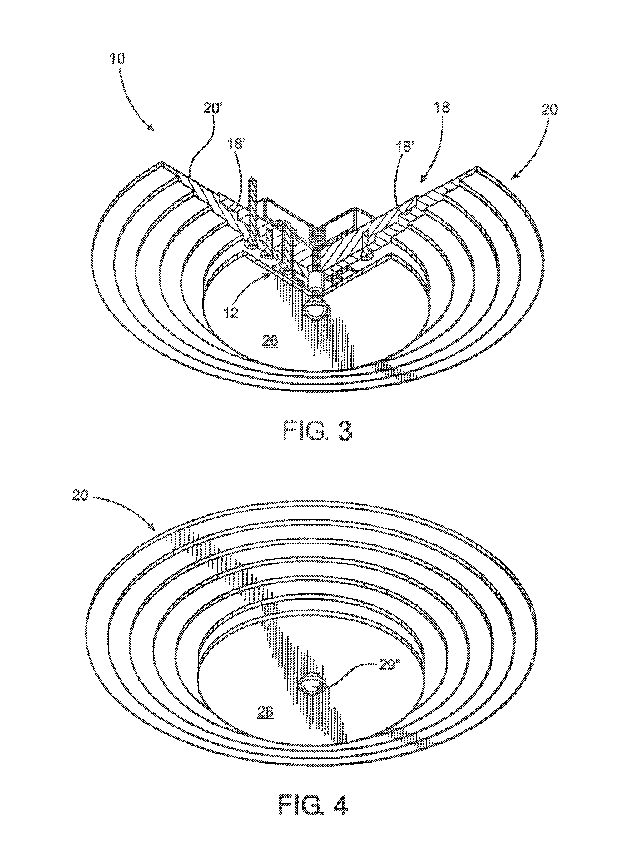
[0050]As shown in the accompanying drawings, the present invention is directed to a light fixture generally indicated as 10. The light fixture 10 is of the type which may be installed in any of a variety of commercial, domestic or other sites and is decorative as well as functional to effectively illuminate a given area or space in the vicinity of the installed location. More specifically, and with reference primarily to FIGS. 1 through 6, the light fixture assembly 10 includes an illumination assembly generally indicated as 12 comprising one or more light emitting diodes 14 connected to electrical control circuitry 16. The control circuitry 16 is preferably in the form of a printed circuit structure 16′ or printed circuit board having the various electrical or circuitry components integrated therein.

[0051]In addition, the light fixture assembly 10 includes a mounting assembly generally indicated as 18 and preferably, but not necessarily, comprising a plate or disk like configuratio...


PUM

PropertyMeasurementUnit
Lengthaaaaaaaaaa
Electrical conductivityaaaaaaaaaa
Currentaaaaaaaaaa

Abstract

A light fixture assembly including an illumination assembly in the form of one or more light emitting diodes is interconnected to an electrical energy source by control circuitry. A mounting assembly supports the illumination assembly and a cover structure is disposed in heat transferring relation to the illumination assembly, wherein the cover structure and / or mounting assembly have enlarged surface areas formed of a heat conductive material, facilitating heat dissipation generated by the illumination assembly into the surrounding environment. At least one connector, formed of an electrically conductive material, is disposed in interconnecting, current conducting relation between a source of electrical energy and the illumination assembly. The mounting assembly is disposed in electrically segregated relation to the connector(s), wherein said interconnecting relation of said one connector at least partially defines an assembled orientation of the illumination assembly and mounting assembly.

Description

CLAIM OF PRIORITY[0001]The present application is a continuation-in-part application of previously filed, application having Ser. No. 13 / 749,156 filed on Jan. 24, 2013, which matured into U.S. Pat. No. 8,789,980 on Jul. 29, 2014, which is a continuation-in-part application of previously filed application having Ser. No. 13 / 018,996 filed on Feb. 1, 2011, which matured into U.S. Pat. No. 8,534,873 on Sep. 17, 2013, which is a continuation-in-part application of previously filed application having Ser. No. 11 / 985,055 filed on Nov. 13, 2007, which matured into U.S. Pat. No. 7,878,692 on Feb. 1, 2011, which is a continuation-in-part of previously filed application having Ser. No. 11 / 985,056 filed on Nov. 13, 2007, which matured into U.S. Pat. No. 7,980,736 on Jul. 19, 2011; the present application is also a continuation-in-part application having Ser. No. 12 / 902,852 filed on Oct. 12, 2010, which matured into U.S. Pat. No. 8,360,614 on Jan. 29, 2013, which is a continuation-in-part applic...

Claims


Application Information

Patent Timeline
IPC IPC(8): F21V29/00F21S8/10F21S8/04F21V9/00
CPCF21V29/22F21S48/328F21S8/04F21V9/00F21V29/262F21V29/2206F21V31/005F21V15/01F21V17/002F21V23/006F21W2121/00F21V29/74F21V29/85F21V23/06F21Y2103/10F21Y2115/10F21V3/061F21V3/062F21S45/47
Inventor SODERMAN, DARYLSTEPPS, DALE B.
Owner SODERMAN DARYL
Learn More