Reactor for atomic layer deposition (ALD), application to encapsulation of an OLED device by deposition of a transparent AI2O3 film

a technology of atomic layer and reactor, applied in the direction of coatings, electroluminescent light sources, electric lighting sources, etc., can solve the problems of device deformation, inability to use, appearance of non-emissive dark spots, etc., and achieve the effect of preventing or preventing the contamination of the substrate by particles

Inactive Publication Date: 2015-07-14
COMMISSARIAT A LENERGIE ATOMIQUE ET AUX ENERGIES ALTERNATIVES
View PDF5 Cites 5 Cited by
  • Summary
  • Abstract
  • Description
  • Claims
  • Application Information

AI Technical Summary

Benefits of technology

[0033]Advantageously, in step a), the substrate is positioned with the surface on which the thin film is to be produced directed downwards. It is thus possible to further reduce the number of particles on the surface of the substrate originating from the lid.
[0037]Thus, according to the invention, the chicanes in the flow of gaseous precursors prevent residual particles from reaching directly the surface of the substrate on which it is desired to deposit the thin film. In other words, the chicanes form as it were an obstacle defining a winding path for the gaseous precursors and thus modify their course relative to a prior-art architecture in which the gaseous precursors are made to flow in permanence by transverse pumping and directly onto the substrate from the inlet orifice toward the outlet orifice during the deposition cycle. In yet other words, the winding path of the gaseous precursors created by the chicanes especially prevents particles from being sprayed directly onto the surface of the substrate. Particulate contamination of the substrates is prevented or at the very least considerably reduced.

Problems solved by technology

This is because, if it is not suitably protected, there is a risk that the device will subsequently degrade, chiefly resulting in the appearance of non-emissive dark spots.
Generally, these thin barrier films are oxides, nitrides or oxynitrides, or, if required, thin metal films, the latter not being able to be used when the OLED(s) is(are) top-emitting devices, in which case the barrier films have to be transparent, necessarily.
These aggregates are undesirable because they are liable to lead to particulate contamination of the substrate, and also to increase the roughness of the thin film [1], [2].
Such a threshold must be set because, as indicated above, particles are disadvantageous when it is desired to deposit defect-free oxide barrier films.
This maintenance is elaborate and expensive, because it involves a complete clean of the machine in which the reactor is incorporated, especially via sandblasting and chemical etching operations.

Method used


Image

  • Reactor for atomic layer deposition (ALD), application to encapsulation of an OLED device by deposition of a transparent AI2O3 film
  • Reactor for atomic layer deposition (ALD), application to encapsulation of an OLED device by deposition of a transparent AI2O3 film
  • Reactor for atomic layer deposition (ALD), application to encapsulation of an OLED device by deposition of a transparent AI2O3 film

Examples


Embodiment Construction

[0043]Other advantages and features of the invention will become apparent on reading the detailed description of the invention given by way of nonlimiting illustration and with reference to the following figures in which:

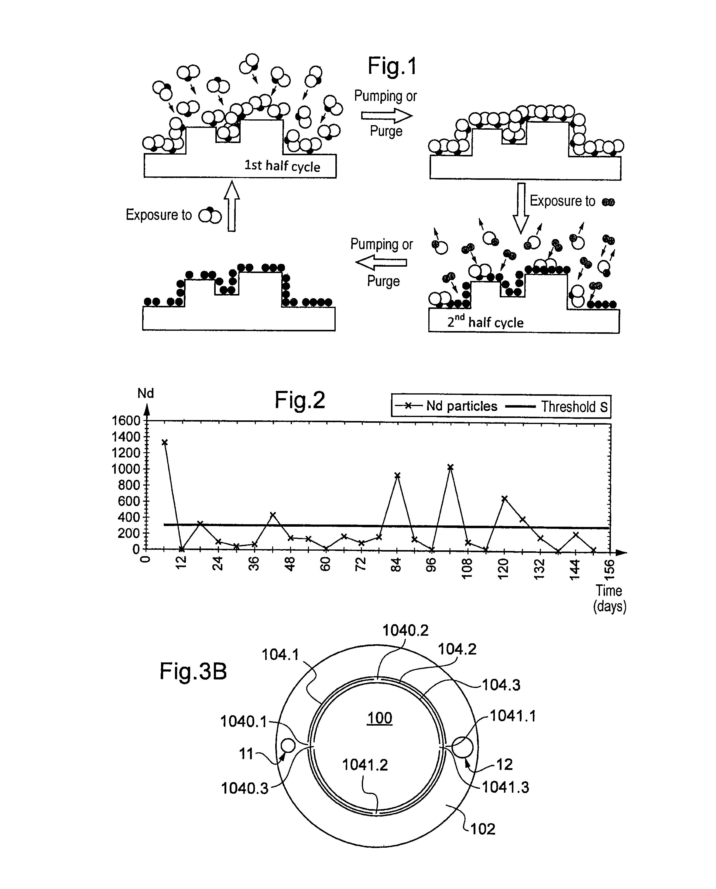
[0044]FIGS. 1 and 2 have already been commented upon above in the preamble. They are therefore not described in greater detail here.

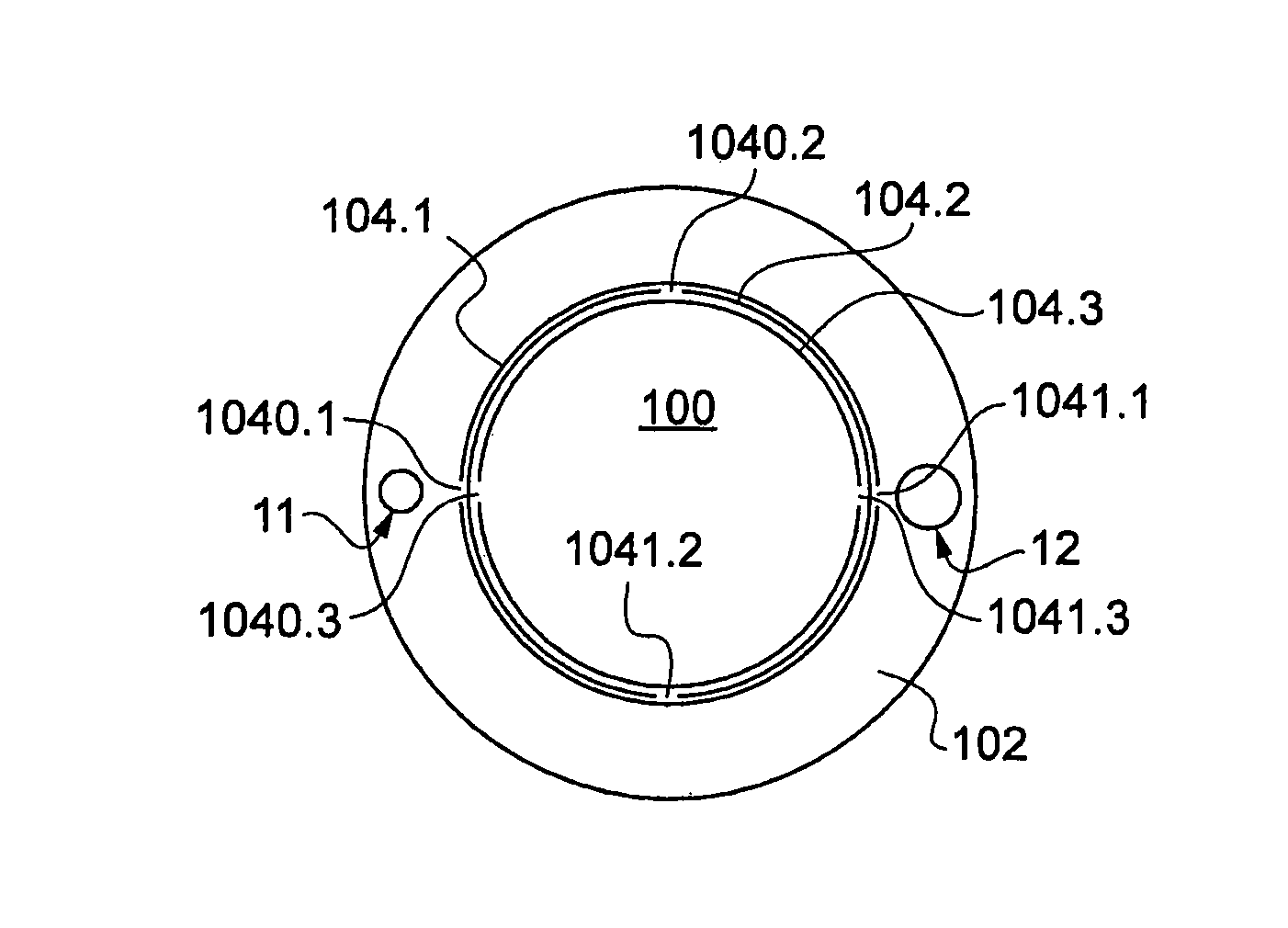
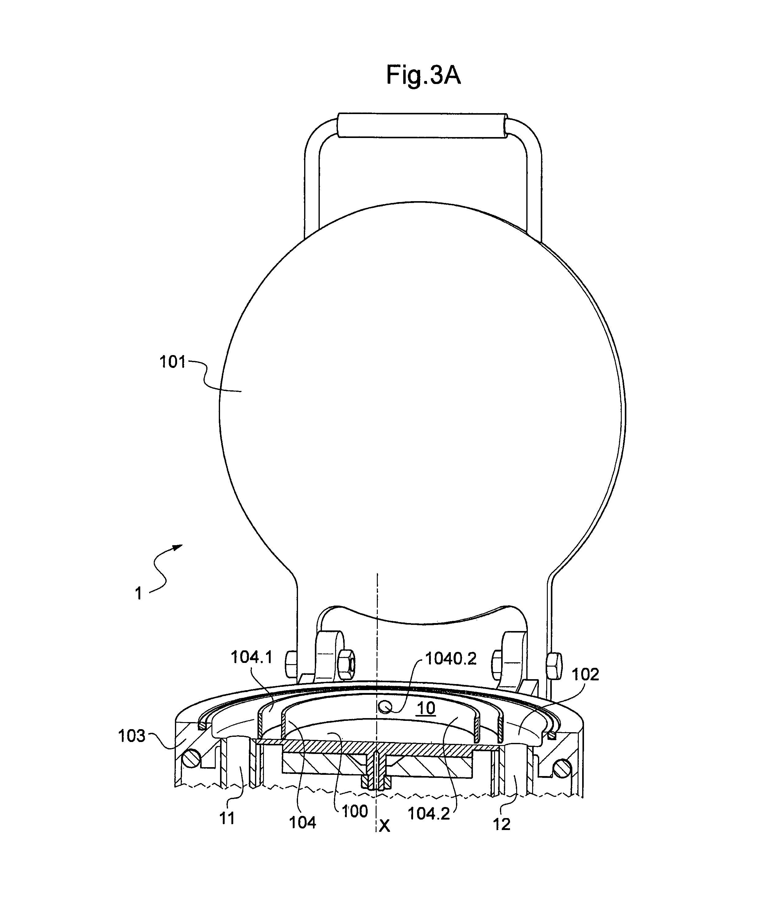
[0045]FIGS. 3A and 3B show an ALD reactor 1 according to the invention. For the sake of clarity, only two apertured walls 104.1, 104.2 according to the invention have been shown in FIG. 3A.

[0046]The ALD reactor 1 according to the invention comprises a reaction chamber 10 having a generally cylindrical shape about its longitudinal X-axis, this reaction chamber comprising a platen 100 and being bounded by a lid 101 that forms the upper surface, a base 102 that forms the lower surface and a sidewall 103 having a generally annular shape. As shown in the open position in FIG. 3A, the lid 101 opens by pivoting about a horizontal axis and thus...


PUM

PropertyMeasurementUnit
angleaaaaaaaaaa
widthaaaaaaaaaa
widthaaaaaaaaaa

Abstract

The present invention relates to a reactor for atomic layer deposition (ALD), comprising a reaction chamber comprising a platen and bounded internally by surfaces; at least one inlet orifice and at least one outlet orifice, each emerging from one of the surfaces bounding the chamber. The reactor furthermore comprises, within it, at least one wall apertured with at least one orifice, the apertured wall extending around the platen and over at least most of the height between the lower surface and the upper surface, at least one orifice in at least one of the apertured walls not facing the inlet orifice so as to form chicanes in the flow of gaseous precursor from each inlet orifice to the platen.

Description

BACKGROUND OF THE INVENTION[0001]1. Technical Field[0002]The present invention relates to a novel atomic layer deposition (ALD) reactor.[0003]The present invention more particularly relates to a novel reactor architecture that allows the density of particles present in the reaction chamber to be considerably reduced.[0004]The invention is advantageously used in the encapsulation of an organic light-emitting diode (OLED) via deposition of a transparent encapsulating film, such as a film of Al2O3.[0005]2. Description of Related Art[0006]At the present time OLED-containing devices are encapsulated in order to protect their sensitive components from gaseous species in the atmosphere (mainly oxygen and water vapour). This is because, if it is not suitably protected, there is a risk that the device will subsequently degrade, chiefly resulting in the appearance of non-emissive dark spots. These dark spots in fact result from the penetration of water vapour into the diode, thereby degrading...

Claims


Application Information

Patent Timeline
Patent Type & Authority Patents(United States)
IPC IPC(8): H01L21/00H01L51/56C23C16/455C23C16/40C23C16/44H01L51/52
CPCH01L51/56C23C16/403C23C16/4401C23C16/455C23C16/45544C23C16/45555C23C16/45591H01L51/5237H10K50/844H05B33/10C23C16/44H10K71/00H10K50/84
Inventor MAINDRON, TONY
Owner COMMISSARIAT A LENERGIE ATOMIQUE ET AUX ENERGIES ALTERNATIVES
Why Eureka
Try Eureka