Single-site localization via multipath fingerprinting

a fingerprinting and single-site technology, applied in the field of single-site localization via multi-path fingerprinting, can solve the problems of low accuracy of this technique, high signal strength variability, invalid classical position location techniques, etc., and achieve the effect of improving the estimated location of the wireless transmitter

Active Publication Date: 2015-07-14
WAVION
View PDF17 Cites 8 Cited by
  • Summary
  • Abstract
  • Description
  • Claims
  • Application Information

AI Technical Summary

Benefits of technology

[0009]This invention improves upon the work of Wax et al. in several aspects. It provides a new approach for wideband signal localization based on exploiting both the directions-of-arrival and the differential-delays of the multipath signals in a single and coherent entity for the fingerprint. This novel fingerprint is derived from a lower dimensional subspace of the spatio-temporal covariance matrix in which the multipath signals reside, also referred to as the signal subspace. The subspace estimation does not require estimation of the directions-of-arrival and differential-delays of the multipath reflections, which is both difficult and computationally intensive problem in rich multipath environments. Moreover, the subspace preferably includes only the dominant reflections, thus forming a rich and robust fingerprint that is used in conjunction with a powerful similarity-profile matching criterion to provide accurate single-site localization. This spatio-temporal fingerprint thus captures effectively the multipath characteristics and enables single-site localization in rich multipath environments. Moreover, this approach is applicable to any wideband signal, provided the signal has a repeatable part. As such, it is applicable to all modern communication technologies, including Wi-Fi and LTE, that use a known fixed signal at the beginning of every packet (i.e., a preamble) for synchronization and channel estimation purposes. In addition, this invention is useful for locating transmitters in both indoor and outdoor environments.
[0012]In one embodiment, the matching of the fingerprints may be performed by searching the database fingerprints for a spatio-temporal signal subspace that maximizes the projection of a received signal sample spatio-temporal covariance matrix onto the subspace. In this embodiment, the method may also include calculating and storing in the database the projection operator corresponding to each location by calculating a space spanned by columns of a matrix A, wherein the columns are composed of direction-delay vectors of signal reflections, and wherein the span of the matrix A is computed from the dominant eigenvectors of the spatio-temporal covariance matrix.
[0014]The method may include combining the estimated location of the transmitter with past estimated locations of the wireless transmitter to produce an improved estimated location of the wireless transmitter. The method may also include combining the estimated location of the transmitter with a second estimated location (or multiple estimated locations) derived from signals received by a second base station (or multiple base stations) from the wireless transmitter to produce an improved estimated location of the wireless transmitter.

Problems solved by technology

Determining the position or location of a wireless emitter (or transmitter) is a well-known problem with both military and commercial applications.
As a result, the classical position location techniques are not valid.
The localization problem is casted as a pattern recognition problem, namely, a database of fingerprints is pre-collected in the desired area to be covered, and the location is determined by comparing the extracted fingerprint to the fingerprint database.
The RSS fingerprint suffers from dependence on many irrelevant parameters such as the orientation of the transmitter and body shadowing, but more critically, it suffers from high signal strength variability caused by constructive and destructive interference between the multipath signals.
As a result, the accuracy of this technique is limited.
In many cases, however, multiple BSs may not be able to receive the signals, in which case the accuracy is very low.
Prior work on this approach, however, was mostly confined to the narrowband signals of the advanced mobile phone system (AMPS) and used only the directions-of-arrival information for creating the fingerprint.

Method used


Image

  • Single-site localization via multipath fingerprinting
  • Single-site localization via multipath fingerprinting
  • Single-site localization via multipath fingerprinting

Examples


Embodiment Construction

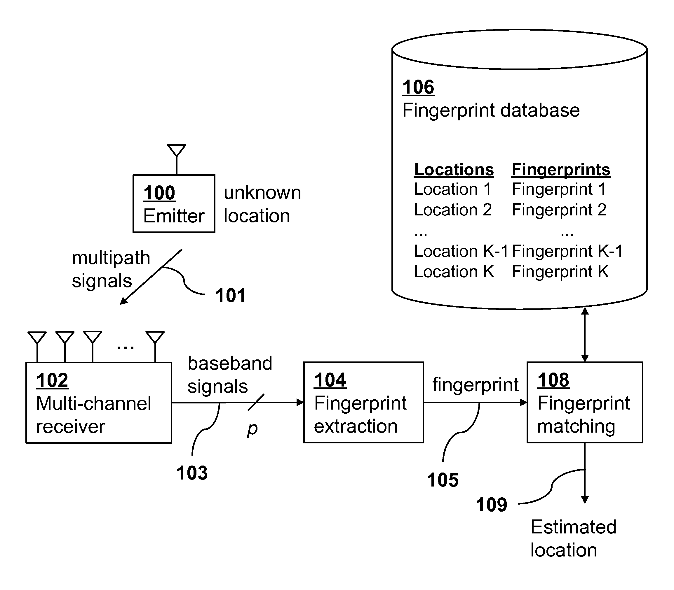
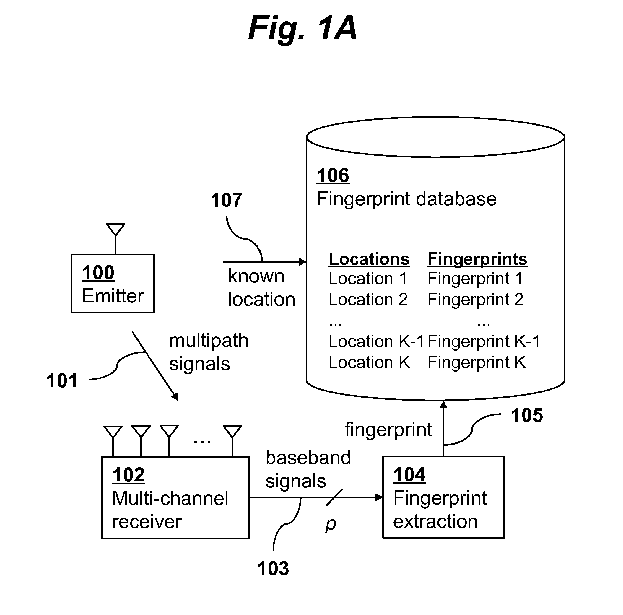
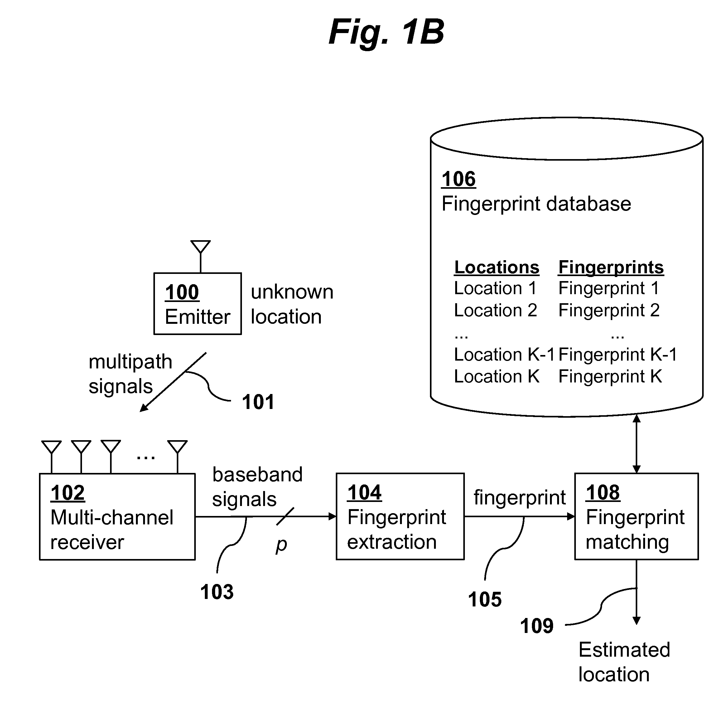
[0018]A general view of a localization technique according to an embodiment of the invention is presented in FIGS. 1A and 1B. The technique includes two phases: an off-line phase, shown in FIG. 1A, and an on-line phase, shown in FIG. 1B. During the off-line phase, fingerprints 105 are collected from one or more emitters 100 at various known locations 107 in the desired geographic coverage area. Signals 101 transmitted from the emitter 100 at a known location propagate through the environment, possibly experiencing severe multipath, and are received by an antenna array and processed by a multi-channel receiver 102 of a BS. After down-conversion to baseband signals 103 by the receiver 102, the received signals are processed by a fingerprint extraction module 104 of the BS which produces the fingerprint 105 from characteristics of the signal. The fingerprint is then stored in a fingerprint database 106 of the BS together with the corresponding known location 107 of the emitter 100. The...


PUM


Abstract

Single-site localization of wireless emitters in a rich multipath environment is presented. The localization method is based on exploiting the spatio-temporal characteristics of the multipath signals, referred to as the multipath fingerprint, as captured by the base station antenna array. The method is applicable to all modern communication techniques such as WiFi and LTE and to any rich multipath environment in indoors and outdoors.

Description

CROSS-REFERENCE TO RELATED APPLICATIONS[0001]This application claims priority from U.S. Provisional Patent Application 61 / 582,598 filed Jan. 3, 2012, which is incorporated herein by reference.FIELD OF THE INVENTION[0002]The present invention relates generally to wireless communications. More specifically, it relates to techniques for determining by a base station the location of wireless emitters using multipath fingerprinting and signal subspace matching.BACKGROUND OF THE INVENTION[0003]Determining the position or location of a wireless emitter (or transmitter) is a well-known problem with both military and commercial applications. Many techniques have been proposed and applied to this problem over the last 70 years. Most of these techniques are based on the assumption that the wireless signal travels from the source to the receiving antennas along the line-of-sight (LOS) path connecting them. The classical position location techniques, direction-of-arrival (DOA), time-of-arrival (...

Claims


Application Information

Patent Timeline
Patent Type & Authority Patents(United States)
IPC IPC(8): H04W24/00H04W64/00G01S5/02
CPCH04W64/00G01S5/0252G01S5/0273
Inventor WAX, MATIKUPERSHTEIN, EVGENY
Owner WAVION
Why Eureka
Try Eureka