Method for transient testing of oil wells completed with inflow control devices

a technology of inflow control and oil well, which is applied in the direction of fluid removal, borehole/well accessories, survey, etc., can solve the problems of reducing the probability of certainty, minimizing and reducing the permeability of the formation, so as to improve the probability of certainty and the effect of improving the productivity of the well

Active Publication Date: 2015-07-21
SAUDI ARABIAN OIL CO
View PDF7 Cites 11 Cited by
  • Summary
  • Abstract
  • Description
  • Claims
  • Application Information

AI Technical Summary

Benefits of technology

[0012]Embodiments of the invention are directed to a method for transient testing of a well completed with one or more ICDs. In particular, various embodiments of the invention provide for a method for transient testing of an oil well completed with one or more ICDs, which determines, for example, reservoir permeability, well skin factor, and ICD characteristic parameters of the well under field conditions, enabling reservoir management and production engineering personnel to assess the effects of formation damage of a well with a higher probability of certainty, and to determine whether stimulation of the well would improve the well's productivity.

Problems solved by technology

Consequently, some of the drilling fluid can penetrate the formation and particles suspended in the mud can partially penetrate pore spaces in the wellbore, reducing formation permeability and causing formation damage around the wellbore.
Formation damage around the wellbore causes additional resistance to fluid flow through the wellbore, which can generate an additional pressure drop or loss of fluid flow into and through the wellbore, minimizing well productivity.
Because these conventional transient testing methods are only able to determine the apparent skin factor as a summation of the well skin factor and the completion skin factor (i.e., does not distinguish between the individual well skin and completion skin factors), petroleum engineers are unable to specifically determine whether the well should be stimulated to improve the well's productivity.

Method used


Image

  • Method for transient testing of oil wells completed with inflow control devices
  • Method for transient testing of oil wells completed with inflow control devices
  • Method for transient testing of oil wells completed with inflow control devices

Examples


Embodiment Construction

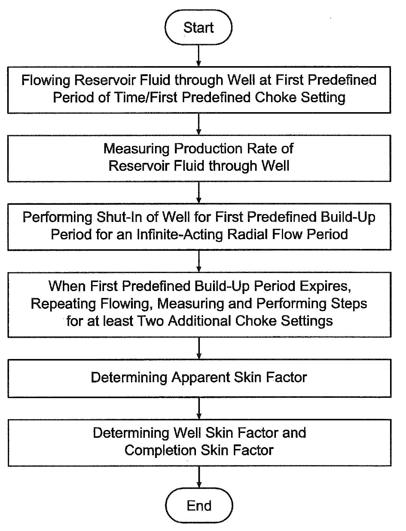
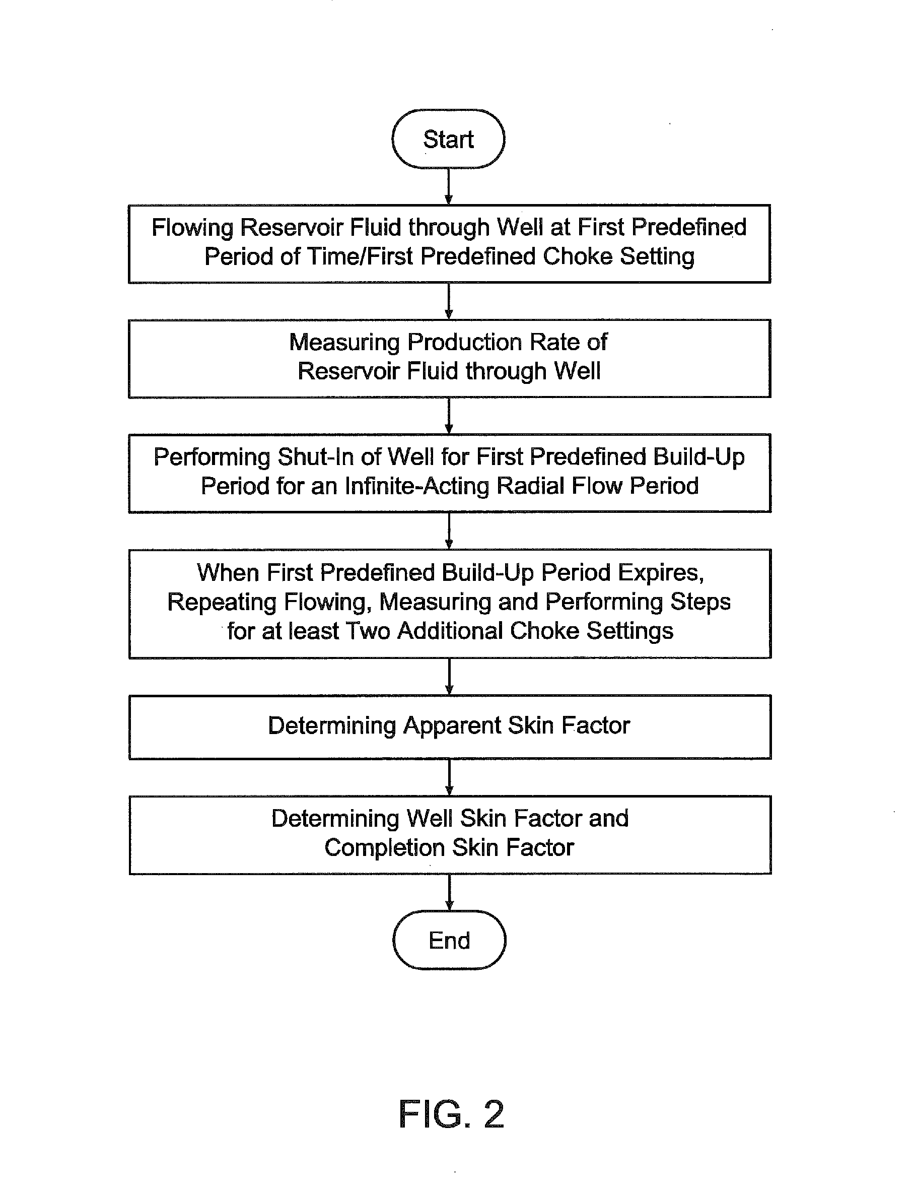
[0019]Although the following detailed description contains many specific details for purposes of illustration, it is understood that one of ordinary skill in the relevant art will appreciate that many examples, variations, and alterations to the following details are within the scope and spirit of the invention. Accordingly, the exemplary embodiments of the invention described herein are set forth without any loss of generality, and without imposing limitations, relating to the claimed invention. Like numbers refer to like elements throughout. Prime notation, if used, indicates similar elements in alternative embodiments.

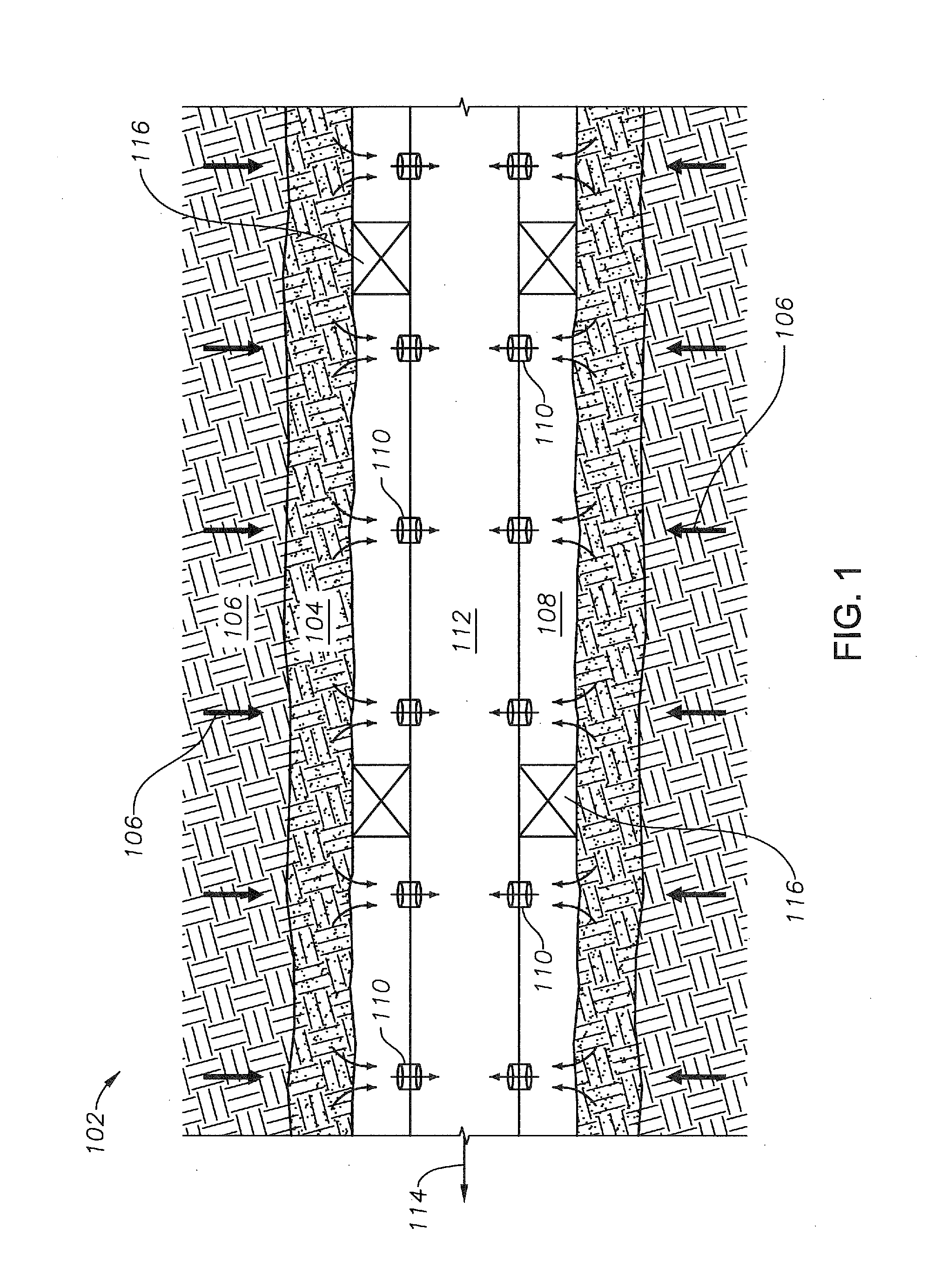
[0020]As used herein, the term “inflow control device” or “ICD” shall be used to refer to a completion hardware device used in a well, which distributes the inflow of a material, for example, oil or gas, evenly through the well. The ICD can create an additional pressure drop that balances or equalizes the wellbore pressure drop caused by, for example, formation dama...


PUM


Abstract

Disclosed is a method for transient testing of an oil well to determine the individual, distinct skin factor components of an apparent skin factor, which includes opening the well to a first predefined choke setting to allow the reservoir fluid to flow through the well for a first predefined period of time, and measuring a production rate of the reservoir fluid through the well, when the first predefined period of time expires. The method further includes performing a shut-in of the well for a first predefined build-up period, and repeating, when the first predefined build-up period expires, the steps of the flowing, the measuring, and the performing for at least two additional choke settings. The distinct skin factor components of the apparent skin factor are determined using a graphical relationship between the determined apparent skin factors and the measured production rates.

Description

RELATED APPLICATION[0001]This application is related to, and claims priority to, U.S. Provisional Patent Application Ser. No. 61 / 603,723, filed on Feb. 27, 2012, the disclosure of which is incorporated by reference in its entirety.BACKGROUND[0002]1. Field of the Invention[0003]Embodiments of the invention generally relate to a method for transient testing of an oil well completed with an inflow control device (ICD), and more particularly, to a method for transient testing of an oil well completed with one or more ICDs, which determine reservoir and well parameters for deciding whether stimulation of the oil well would improve well productivity.[0004]2. Description of the Related Art[0005]Transient well testing provides an indirect determination of reservoir and well parameters for optimizing the productivity of an oil well. Transient testing is one of the most important tools in a spectrum of diagnostic tools used by petroleum engineers to characterize hydrocarbon assets and predict...

Claims


Application Information

Patent Timeline
Patent Type & Authority Patents(United States)
IPC IPC(8): E21B47/10E21B43/12E21B43/14
CPCE21B47/10E21B43/12E21B43/14
Inventor RAHMAN, NOOR M. ANISURAL-THAWAD, FAISAL M.BINAKRESH, SAUD A.
Owner SAUDI ARABIAN OIL CO
Why Eureka
Try Eureka