Power module and the method of packaging the same

a power module and power technology, applied in the field of power modules, can solve problems such as power modules

Active Publication Date: 2015-07-21
XINTEC INC
View PDF5 Cites 3 Cited by
  • Summary
  • Abstract
  • Description
  • Claims
  • Application Information

AI Technical Summary

Benefits of technology

[0036]In the invention, an inductor and a connection layer in the power module are directly formed by deposition or electroplating, which significantly lowers the cost and simplifies fabrication. Integrating chip-scale packaged transistors and inductor further improves footprint and saves the problem of matching transistors with inductors for designers. Furthermore, a wide variety of PWM controllers can be incorporated as long as their driving signal frequencies are on par with the switching speed of transistors in the power module to promote power management design efficiency.

Problems solved by technology

However, the power modules mentioned above are inconvenient when being incorporated with different PWM controllers and still have room for improvement.

Method used


Image

  • Power module and the method of packaging the same
  • Power module and the method of packaging the same
  • Power module and the method of packaging the same

Examples


Embodiment Construction

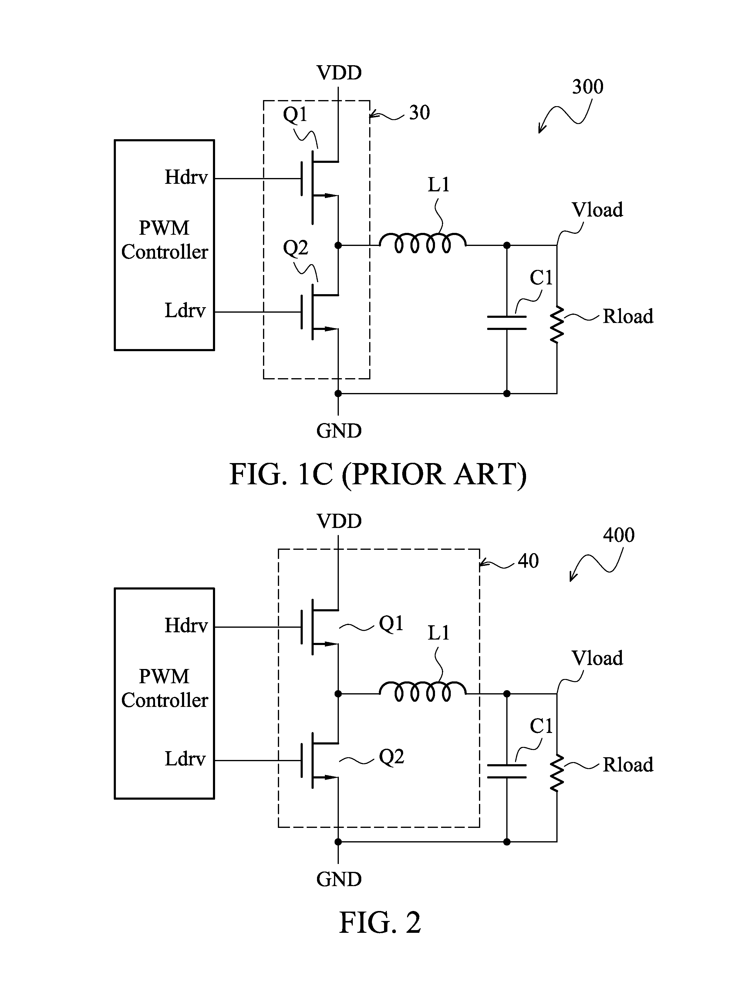
[0016]FIG. 2 shows a circuit diagram of power module 40 according to an embodiment of the invention and a corresponding power converter 400 using the power module 40. The power converter 400 comprises a power module 40, which integrates a first transistor Q1, a second transistor Q2, and an inductor L1 into a package; a PWM controller controlling ON / OFF states of the first transistor Q1 and the second transistor Q2 by sending a first control signal Hdry and a second control signal Ldry to gates of the transistors Q1 and Q2, respectively; and a capacitor C1.

[0017]When the first control signal Hdry switches the first transistor to ON, the second control signal Ldry switches the first transistor to OFF. Thus, the inductor L1 and the capacitor C1 are charged via the first transistor Q1 by an input voltage VDD. When the first control signal Hdry switches the first transistor to OFF, the second control signal Ldry switches the first transistor to ON. Thus, the inductor L1 and the capacitor...


PUM

PropertyMeasurementUnit
inductanceaaaaaaaaaa
conductiveaaaaaaaaaa
inductanceaaaaaaaaaa

Abstract

A power module includes a substrate; a conductive path layer formed on the substrate with a specific pattern as an inductor; a connection layer being formed on the substrate and electrically connected to a first terminal of the inductor; and a first transistor, electrically mounted on the substrate through the connection layer.

Description

CROSS-REFERENCE TO RELATED APPLICATIONS[0001]This application claims the benefit of U.S. Provisional Application No. 61 / 437,495, filed on Jan. 28, 2011, the contents of which are incorporated herein by reference.BACKGROUND OF THE INVENTION[0002]1. Field of the Invention[0003]The invention relates to a power module, and in particular, relates to a method of packaging the power module.[0004]2. Description of the Related Art[0005]Power converters have been widely utilized in commercialized power management category. For example, DC / DC conversion, or providing constant current flow. FIG. 1A shows a diagram of a traditional power converter 100. The power converter 100 comprises a pulse width modulating controller (PWM controller), NMOSFETs Q1 and Q2, an inductor L1, and a capacitor C1. The PWM controller controls ON / OFF state of the NMOSFETs Q1 and Q2 by providing a first control signal Hdry to a gate of the NMOSFET Q1 and providing a second control signal Ldry to a gate of the NMOSFET Q...

Claims


Application Information

Patent Timeline
Patent Type & Authority Patents(United States)
IPC IPC(8): H01L29/06H02M3/00H01L25/16H01L23/64H01F17/00H02M3/155H01L27/06H04B1/02H01L23/00H01L25/07
CPCH02M3/155H01F17/0006H01L23/645H01L25/165H02M3/00H01F2017/0046H01F2017/0073H01F2017/0086H01L24/16H01L25/072H01L2224/16225H01L2924/13091H01L2924/16195H01L2924/19105H02M3/003
Inventor YIU, HO-YINLIU, CHIEN-HUNGYANG, WEI-CHUNGLOU, BAI-YAO
Owner XINTEC INC
Why Eureka
Try Eureka