Fast reactor

a fast reactor and fast technology, applied in the direction of nuclear reactors, greenhouse gas reduction, nuclear elements, etc., can solve the problems of deterioration of the heat exchange function, loss of the heat balance difficulty in providing a sealing structure having a sufficient sealing property, so as to improve the reliability of the fast reactor, prevent the effect of lowering the power generation efficiency of the fast reactor

Active Publication Date: 2015-07-28
KK TOSHIBA
View PDF12 Cites 6 Cited by
  • Summary
  • Abstract
  • Description
  • Claims
  • Application Information

AI Technical Summary

Benefits of technology

[0011]The present invention has been made in view of the above circumstances. The object of the present invention is to provide a fast reactor having a high primary coolant sealing property and an excellent maintainability.
[0040]According to the present invention, in the fast reactor comprising the reactor vessel accommodating therein the core and the coolant, the pump for coolant, which is configured to pressurize the coolant that has passed through an intermediate heat exchanger so as to be cooled, is disposed between the inner surface of the reactor vessel and the bulkhead, and the neutron shield is disposed below the pump for coolant. In addition, the upper supporting plate supporting the neutron shield is disposed between the pump for coolant and the neutron shield. The upper supporting plate has the opening through which the pressurized coolant from the pump for coolant passes. Disposed between the outlet of the pump for coolant and the upper supporting plate is the coolant guide mechanism configured to guide the pressurized coolant from the pump for coolant toward the neutron shield through the opening of the upper supporting plate. Thus, the coolant of a lower temperature, which has been cooled by the intermediate heat exchanger and pressurized by the pump for coolant, can be guided by the coolant guide mechanism toward the neutron shield through the opening of the upper supporting plate. Therefore, there is no possibility that the coolant of a lower temperature, which has been pressurized by the pump for coolant, leaks to the coolant of a higher temperature, which has been heated by the core, through the bulkhead, whereby it is possible to improve a sealing property between the coolant of a lower temperature, which has been pressurized by the pump for coolant, and the coolant of a higher temperature, which has been heated by the core. As a result, lowering of a power generation efficiency of the fast reactor can be prevented, as well as reliability of the fast reactor can be enhanced.

Problems solved by technology

Thus, it is difficult to provide a sealing structure having a sufficient sealing property.
In this case, a temperature difference between the inlet and the outlet of the intermediate heat exchanger 15 is possibly decreased, resulting in deterioration of the heat exchanging function.
Thus, a heat balance of the fast reactor 1 may be lost, which induces a large impact on an output of a plant.
Further, since a huge cask for storing these equipments or for bringing these equipments to a disposal place is needed, an enormous cost is required.

Method used


Image

  • Fast reactor
  • Fast reactor
  • Fast reactor

Examples


first embodiment

[0060

[0061]A first embodiment of the present invention will be described herebelow with reference to the drawings.

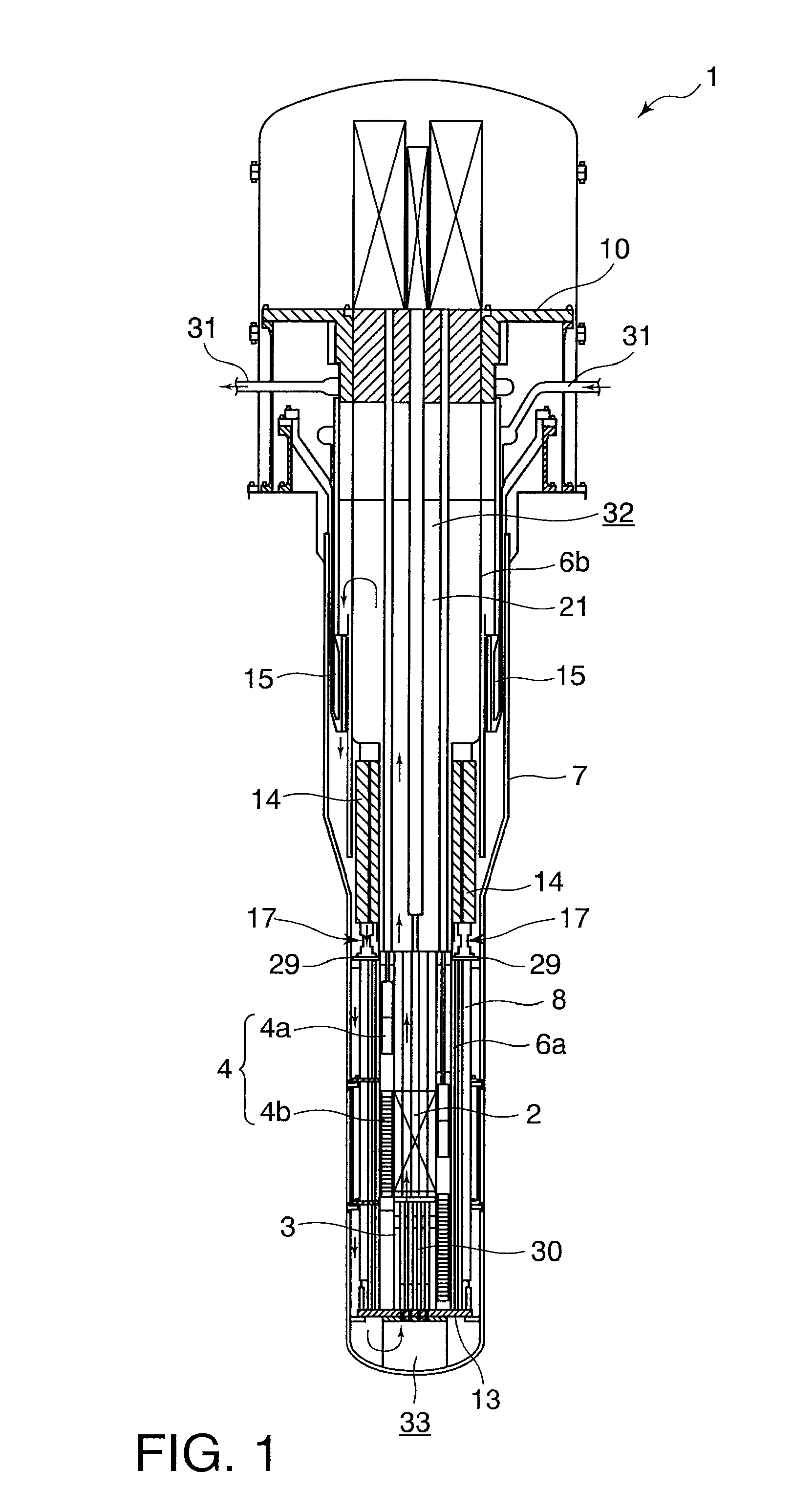
[0062]FIG. 1 to 6 are views showing a fast reactor in the first embodiment of the present invention.

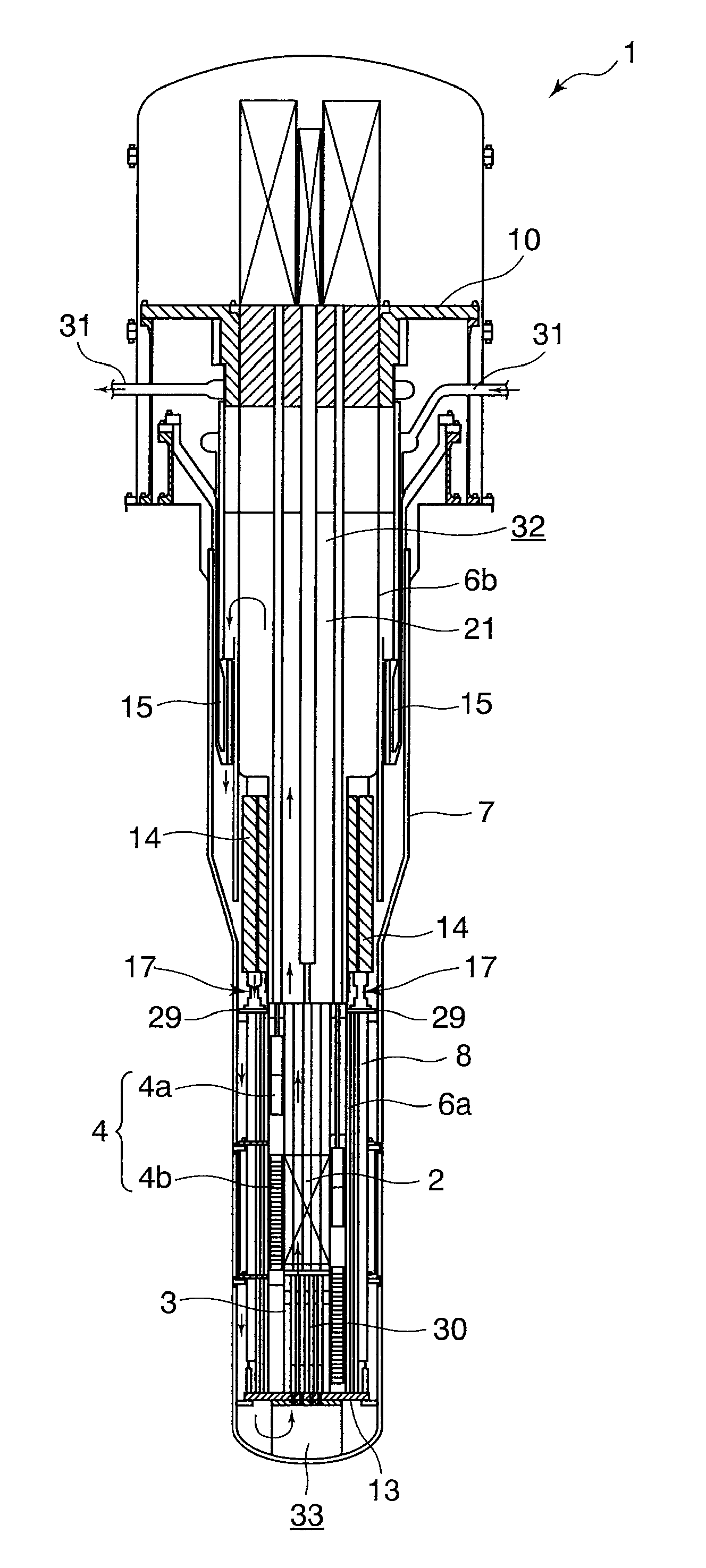
[0063]At first, a fast reactor 1 in this embodiment is generally described with reference to FIG. 1.

[0064]As shown in FIG. 1, the fast reactor 1 includes: a reactor vessel 7 accommodating there in a core 2 formed of a nuclear fuel assembly containing plutonium, and a primary coolant (coolant) 21 formed of liquid sodium; a core support 13 disposed in the reactor vessel 7 so as to support the core 2 from below; a core barrel 3 disposed on the core support 13 so as to surround the core 2 from a lateral side; a reflector 4 disposed so as to surround the core barrel 3; and an upwardly extending bulkhead 6 disposed on the core support 13 so as to surround the core 2, the core barrel 3 and the reflector 4 from the lateral side. The reflector 4 is composed of a neutron reflecting ...

second embodiment

[0091

[0092]Next, a second embodiment of the present invention is described with reference to FIG. 7. FIG. 7 is a view showing a coolant guide mechanism in the second embodiment of the present invention.

[0093]The second embodiment shown in FIG. 7 is substantially the same as the first embodiment shown in FIGS. 1 to 6, excluding that respective nozzles are connected to an upper header through spherical seating seals. In the second embodiment shown in FIG. 7, the same elements as those of the first embodiment shown in FIGS. 1 to 6 are shown by the same reference numbers, and detailed description thereof is omitted.

[0094]As shown in FIG. 7, respective nozzles 19 of a coolant guide mechanism 17 are connected to an upper header 18 through spherical seating seals 19b. Thus, each nozzle 19 can be optionally inclined within a predetermined range with respect to the upper header 18. Therefore, a manufacturing tolerance and an installation tolerance of the coolant guide mechanism 17 can be abs...

third embodiment

[0096

[0097]Next, a third embodiment of the present invention is described with reference to FIG. 8. FIG. 8 is a view showing a coolant guide mechanism in the third embodiment of the present invention.

[0098]The third embodiment shown in FIG. 8 is substantially the same as the first embodiment shown in FIGS. 1 to 6, excluding that the coolant guide mechanism includes a pipe passing through an upper supporting plate, with one end of the pipe being engaged with an upper header, and the other end thereof being connected to a core support. In the third embodiment shown in FIG. 8, the same elements as those of the first embodiment shown in FIGS. 1 to 6 are shown by the same reference numbers, and detailed description thereof is omitted.

[0099]As shown in FIG. 8, a coolant guide mechanism 17 includes an annular upper header 18 mounted on an outlet 14b of an electromagnetic pump 14, and a pipe 22 passing through an upper supporting plate 29, with one end 22a of the pipe 22 being engaged with ...


PUM


Abstract

A fast reactor 1 includes: a reactor vessel 7 accommodating therein a core 2 and a primary coolant 21; a core support 13 supporting the core 2 from below; and a bulkhead 6 disposed on the core support 13, the bulkhead 6 extending upward and surrounding the core 2 from a lateral side. Between an inner surface of the reactor vessel 7 and the bulkhead 6, there is disposed an intermediate heat exchanger 15 configured to cool the primary coolant 21, and an electromagnetic pump 14 configured to pressurize the cooled primary coolant 21. A neutron shield 8 supported by an upper supporting plate 29 from above is disposed below the electromagnetic pump 14. The upper supporting plate 29 has an opening 29a. Between an outlet 14b of the electromagnetic pump 14 and the upper supporting plate 29, there is disposed a coolant guide mechanism 17 configured to guide the pressurized primary coolant 21 from the electromagnetic pump 14 to the neutron shield through the opening 29a of the upper supporting plate 29.

Description

[0001]This application is a U.S. National Phase Application under 35 USC 371 of International Application PCT / JP2010 / 057429 filed Apr. 27, 2010.FIELD[0002]The present invention relates to a fast reactor, in particular, a fast reactor having a high coolant sealing property and an excellent maintainability.BACKGROUND[0003]In a fast reactor, an effort for reducing a leakage amount of coolant from a sealing part has been conventionally exerted. The below Patent Document 1 shows an example of a conventional fast reactor, which is shown in FIG. 15.[0004]As shown in FIG. 15, the fast reactor 1 described in Patent Document 1 includes a core 2 formed of a nuclear fuel assembly. The core 2 has a substantially cylindrical shape as a whole. An outer circumference of the core 2 is surrounded by a core barrel 3. A reflector 4 surrounding the core barrel 3 is located outside the core barrel 3. Outside the reflector 4, there is disposed a bulkhead 6 that surrounds the reflector 4 and constitutes an...

Claims


Application Information

Patent Timeline
Patent Type & Authority Patents(United States)
IPC IPC(8): G21C15/00G21C1/32G21C1/02G21C15/247G21C15/02G21C11/02
CPCG21C1/322G21C1/02G21C15/02G21C15/247G21C11/022Y02E30/34Y02E30/30
Inventor INATOMI, TAKANARIEBIHARA, AYANONAKAMURA, HIROSHIKOBAYASHI, HIDEOHASEGAWA, KATSUSHI
Owner KK TOSHIBA
Why Eureka
Try Eureka