Modular intraocular lens injector

a module and intraocular lens technology, applied in the field of apparatus for inserting artificial intraocular lens, can solve the problems of relative difficulty in holding the device straight during operation, delicate operation requiring extremely fine control, etc., and achieve the effect of minimizing resistance forces

Active Publication Date: 2015-08-04
ASICO
View PDF71 Cites 5 Cited by
  • Summary
  • Abstract
  • Description
  • Claims
  • Application Information

AI Technical Summary

Benefits of technology

[0012]It is an object of the present invention to provide an IOL injector which has a simple construction while providing excellent guidance of the plunger in the main body.
[0021]For securing the plunger against rotation, the barrel portion of the main body may be provided with a substantially longitudinal internal groove in an inner surface of the barrel portion or with a substantially longitudinal slot in a sidewall of the barrel portion, and the guide element may carry a laterally protruding stop element extending laterally into said groove or slot so as to prevent twisting of the plunger relative to the main body. In this case, the guide element even takes on a triple function: guiding the plunger, holding the plunger needle, and securing the plunger against rotation. These three functions are united in a single element in a very simple and elegant fashion, enabling the injector to be assembled and disassembled (e.g. for cleaning purposes) in an extremely simple fashion while providing excellent control to the surgeon.
[0026]In order to avoid jamming, it is preferred that the length of the bearing surface is at least 1.5 times its diameter. For avoiding unnecessarily high resistance forces, it is preferred that the length of the bearing surface is not more than five times its diameter, preferably not more than three times the diameter.
[0030]The retaining element may be a spring-loaded sphere, in particular, a jewel sphere made, e.g., from sapphire or ruby, minimizing resistance forces. However, other types of spring-loaded elements, e.g. a nose on an elastically bendable arm, are conceivable.

Problems solved by technology

While such a device does permit exact guiding of the plunger, the surgeon needs both hands for operating the device, and it is relatively difficult to hold the device straight during operation.
This is a very delicate operation requiring extremely fine control.

Method used


Image

  • Modular intraocular lens injector
  • Modular intraocular lens injector
  • Modular intraocular lens injector

Examples


Embodiment Construction

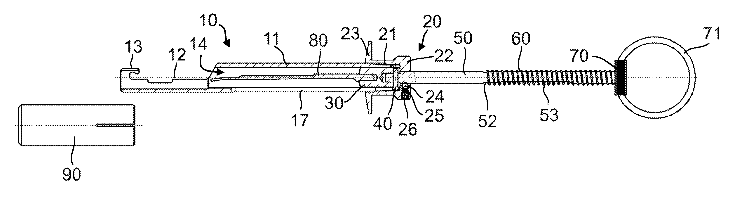
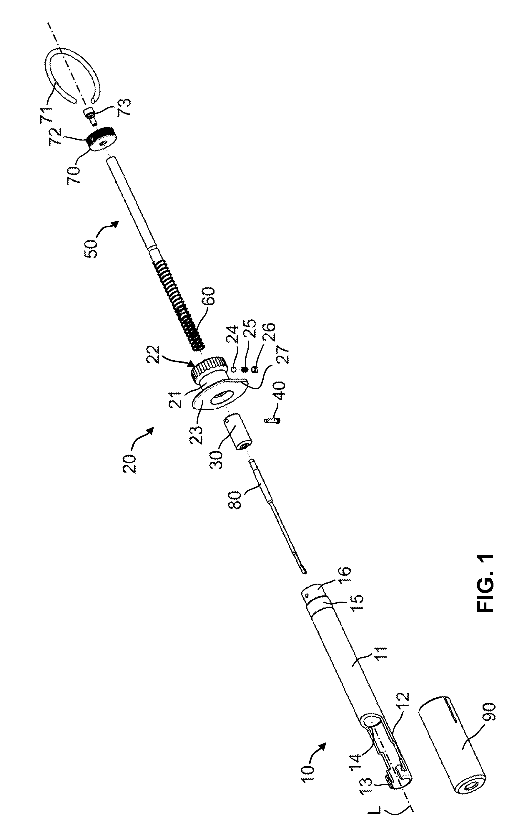
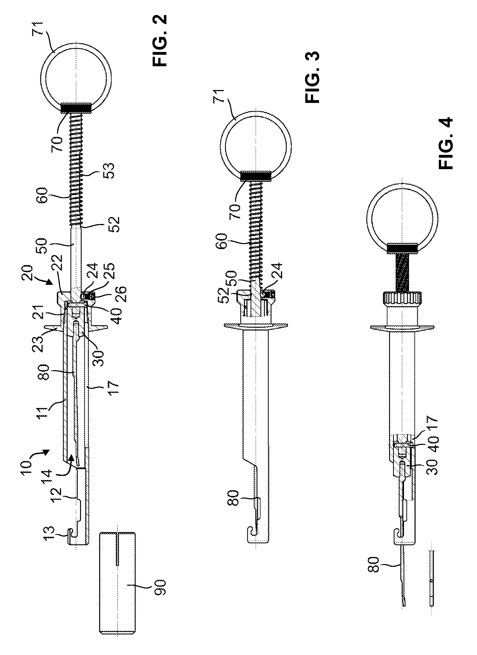
[0049]FIGS. 1-4 illustrate, in various views and states, a preferred embodiment of an IOL injector according to the present invention. The injector comprises an injector housing or injector main body 10 in which a plunger 50 is guided for longitudinal displacement along a central longitudinal axis L.

[0050]Main body 10 has a tubular barrel portion 11 defining a longitudinal lumen or passage 14 extending along the longitudinal axis L. Passage 14 is radially delimited by a substantially circumferential sidewall defining a cylindrical inner surface. A cartridge-receiving portion 12 distally adjoins barrel portion 11, extending away from barrel portion 11 in a distal direction. Cartridge-receiving portion 12 has structures such as hooks 13 for releasably holding a lens cartridge, in which an IOL can be provided for implantation into a patient's eye. Such cartridges are well known in the art and are widely used. Example of lens cartridges which might be used in conjunction with the presen...


PUM


Abstract

An injector for inserting an intraocular lens into an eye, comprising a main body (10) and a plunger (50). A guide element (30) is connected to the distal end of the plunger to laterally guide the plunger during movement along a longitudinal axis (L). The distal end of the guide element has a structure for fastening a plunger needle to the guide element. A radial guide pin (40) is in aligned radial bores of the guide element and plunger and extends into a longitudinal slot (17) of the main body to prevent twisting and to secure the guide element to the plunger. A retaining element (24) interacts with a running surface on the perimeter of the plunger, the running surface having a variable radial distance from the longitudinal axis so as to cause an axial resistance force which depends on the axial position of the plunger.

Description

TECHNICAL FIELD[0001]The present invention relates to an apparatus for inserting an artificial intraocular lens into the eye of a patient during cataract surgery. This type of device is often generally referred to as an intraocular lens injector.PRIOR ART[0002]In cataract surgery, an opaque natural lens in a patient's eye is replaced by an artificial intraocular lens (IOL). In this procedure, the natural lens is first removed, usually by phacoemulsification. Then the artificial IOL is inserted. A variety of techniques can be used for the insertion step. Traditionally, surgeons have introduced the lens into the eye with the aid of surgical forceps. Alternatively, a specifically adapted insertion apparatus, in the following referred to as an IOL injector, may be used. Such a device generally comprises a sleeve-like main body and a plunger longitudinally displaceable within the main body for advancing an IOL in a deformed (e.g., rolled or folded) state through a small-diameter nozzle i...

Claims


Application Information

Patent Timeline
Patent Type & Authority Patents(United States)
IPC IPC(8): A61F2/16
CPCA61F2/167A61F2/1678
Inventor MEYER, ROLF
Owner ASICO
Why Eureka
Try Eureka