
Nucleus pulposus spinal implant and method of using the same

a technology of spinal implants and nucleus pulposus, which is applied in the field of spinal implants for degenerated, herniated or ruptured intervertebral discs, can solve the problems of tissue interaction and/or rejection of implants, reduce the likelihood of biological reactions, and premature material breakdown, so as to improve the capabilities of spinal implants, reduce the degree of invasiveness of surgery and the subsequent development of scar tissue within the body.

Active Publication Date: 2015-08-04
VONGUNTEN ERIC R
View PDF6 Cites 0 Cited by
  • Summary
  • Abstract
  • Description
  • Claims
  • Application Information

AI Technical Summary

Benefits of technology

The present invention and method offer an optimal prosthetic environment for replacing a degenerated or damaged spinal disc. The void within the disc provides a safe space for the implant, reducing the likelihood of biological reaction, premature material breakdown, tissue interaction, and rejection of the implant. By leaving the overlying structures as intact as possible and hardening the implant within the body, the life expectancy and viability of the implant are improved over those known in the prior art. The device and method minimize damage to the spine, allowing for proper rehabilitation of the patient and keeping all other avenues of addressing issues relating to the disc still available to the surgeon and patient. The device and method also maximize retention of the patient's existing range of motion and improve or recapture any lost range of motion through proper rehabilitation of the patient.

Problems solved by technology

Since the annulus fibrosus is naturally avascular, this reduces the likelihood of biological reaction, premature material breakdown, tissue interaction and / or rejection of the implant.

Method used


Image

  • Nucleus pulposus spinal implant and method of using the same
  • Nucleus pulposus spinal implant and method of using the same
  • Nucleus pulposus spinal implant and method of using the same

Examples


second embodiment

[0055]FIG. 12 shows implant receptacle in accordance with the present invention and is generally indicated at 236. Implant receptacle 236 include an outer wall 238 which bounds and defines a cavity 240, and a one way port 242. Implant receptacle further includes an outgassing collection tube 256 which preferably is formed as part of outer wall 238. Collection tube 256 preferably includes a first region 256a comprising a semi-permeable membrane, and a second region 256b which may possibly be comprised of a semi-permeable membrane. Collection tube 256 terminates in an exhaust port 258. As the implant substance (not shown) is introduced into cavity 240, air in cavity 240 crosses over the semi-permeable membrane in first and second regions 256a, 256b. Additionally, the semi-permeable membrane allows gas that is produced during hardening of the implant substance to pass into collection tube 256 and be evacuated from implant receptacle 236 through exhaust port 258. Eventually, the hardeni...

third embodiment

[0056]FIG. 13 shows an implant receptacle in accordance with the present invention, generally indicated at 336. Implant receptacle 236 includes a first outer wall 338a and a second outer wall 338b. Both of the first and second outer walls 338a, 338b are made from a silicone elastomeric material. First outer wall 338a bounds and defines a cavity 340 into which the implant substance is introduced through a way-one-valved port 342. Implant receptacle 236 further includes a collection tube 356 having a first region 356a comprised of a semi-permeable membrane, and a second region 356b possible comprised of a semi-permeable membrane. As with the previous embodiment, collection tube 356 terminates in an exhaust port 358 and functions in the same manner as collection tube 256 and exhaust portion 258. In accordance with a specific feature of the present invention, second outer wall 338b is separated from first outer wall 338a by a gap 360. An intake port 362 and an outflow port 364 are provi...


PUM

PropertyMeasurementUnit
wavelengthaaaaaaaaaa
lengthaaaaaaaaaa
sizeaaaaaaaaaa

Abstract

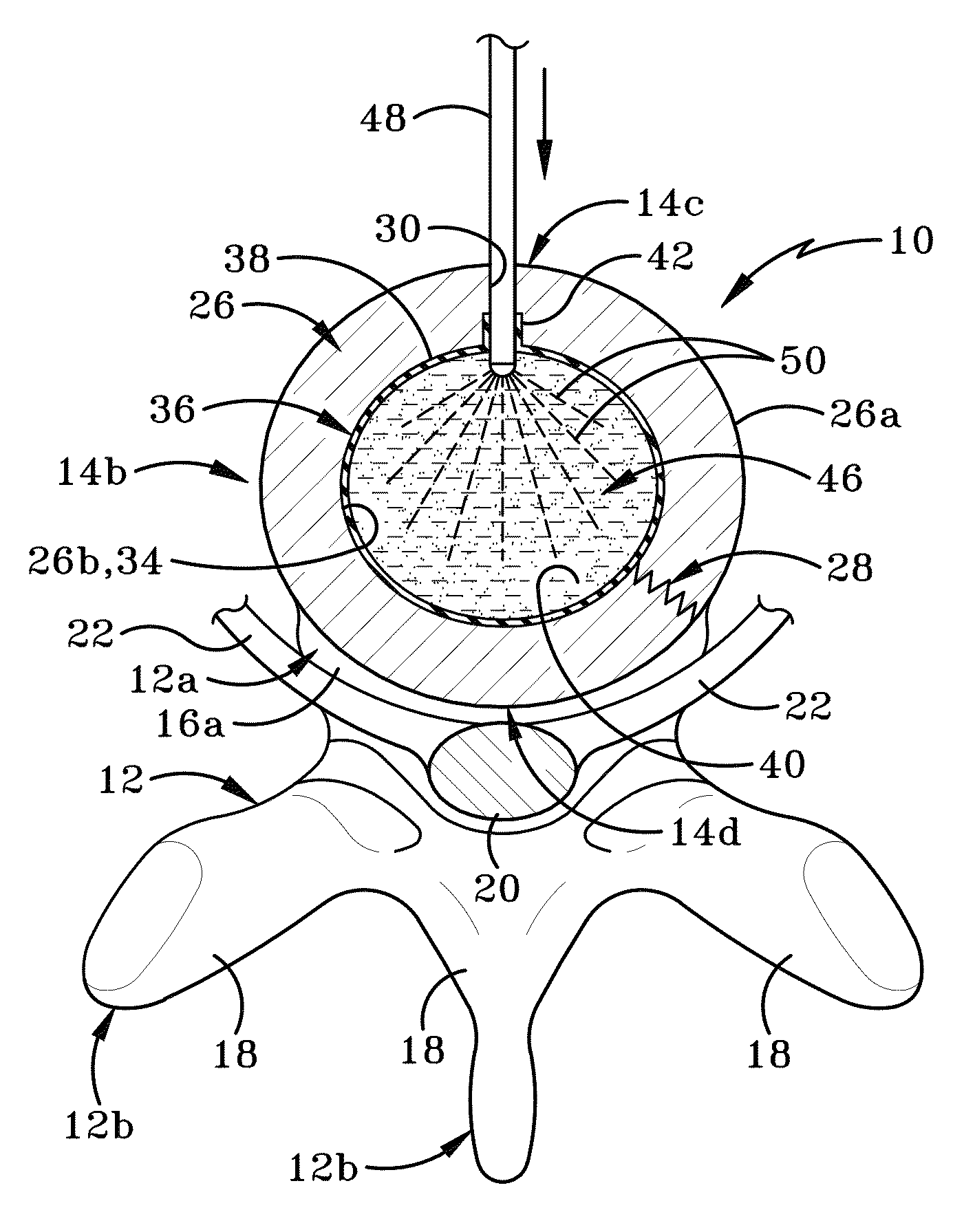
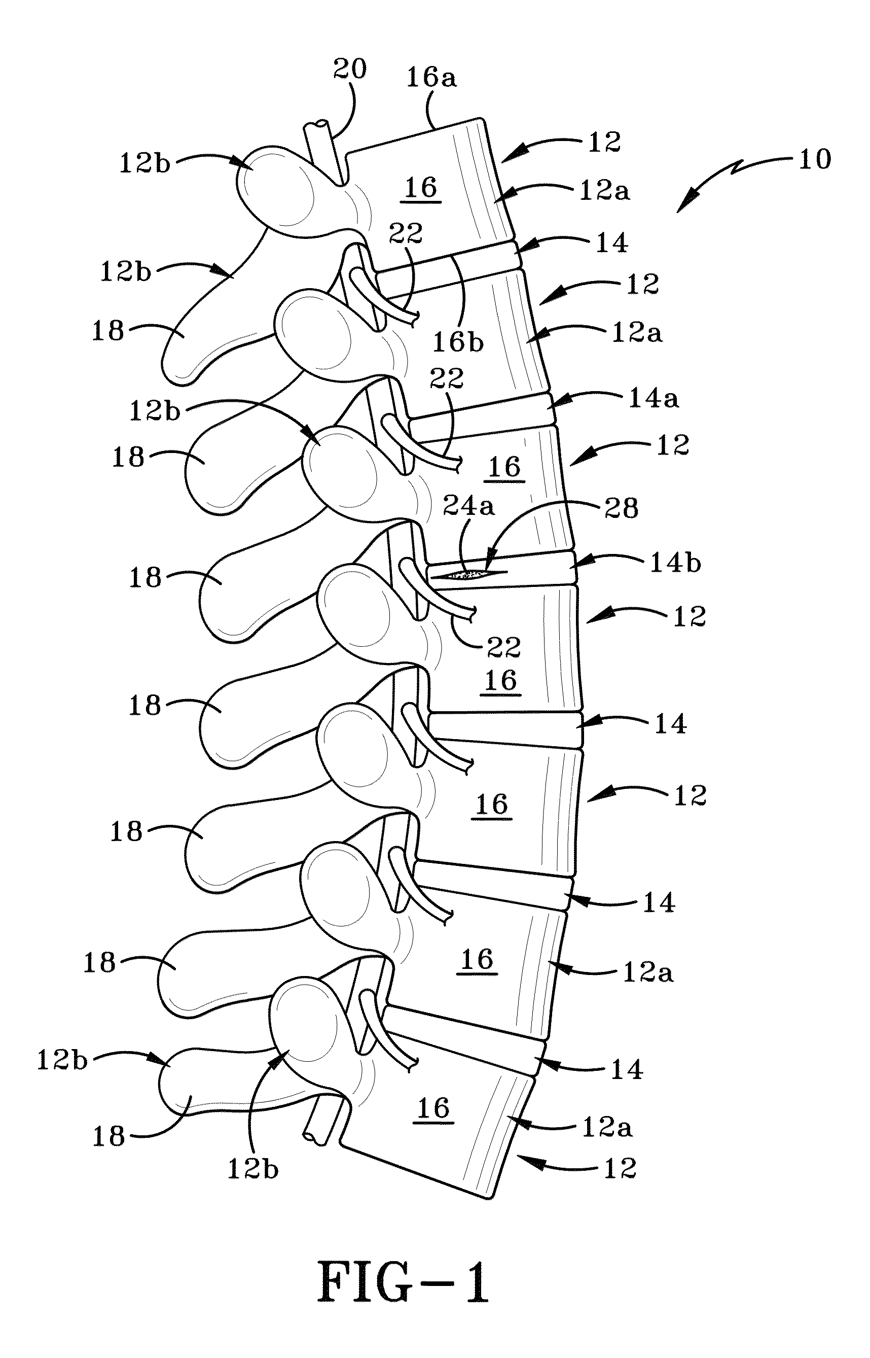
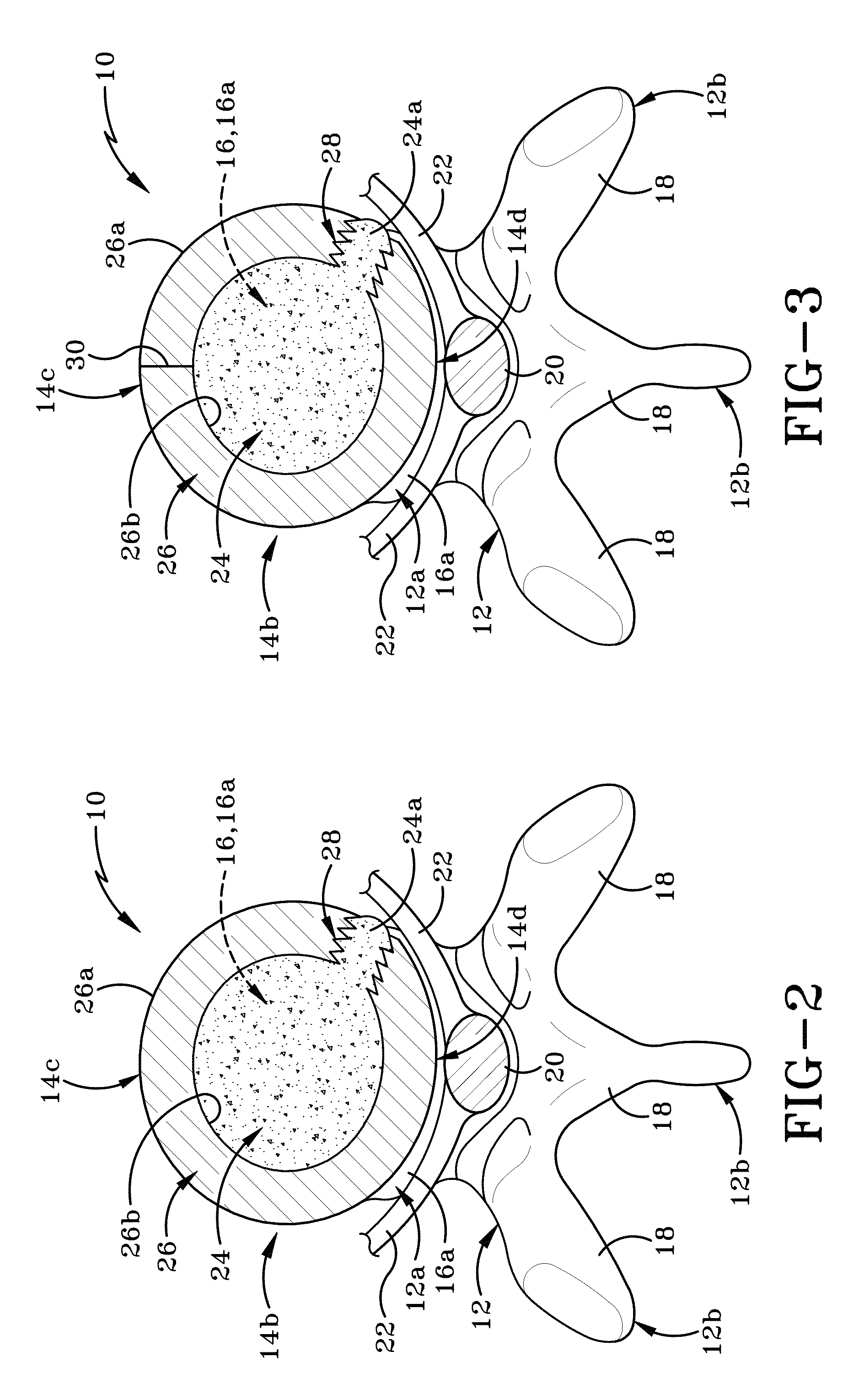
An implant configured to completely replace degenerated or damaged nucleus pulposus in an intervertebral disc. The implant comprises a silicone elastomer shell that is implanted into a void within the annulus fibrosus created by at least partial removal of the nucleus pulposus therefrom. A colloidal suspension of platinum cured silicone-based polymer and carbon nanotubes is injected into the elastomer shell. The colloidal suspension is irradiated with electromagnetic radiation, particularly infrared or near infrared light, to the point that it hardens. The hardened implant becomes a mechanical replacement for the original nucleus pulposus in the intervertebral disc.

Description

CROSS-REFERENCE TO RELATED APPLICATIONS[0001]This application claims the benefit of U.S. Provisional Patent Application Ser. No. 61 / 644,063 filed May 8, 2012.BACKGROUND OF THE INVENTION[0002]1. Technical Field[0003]This invention relates generally to treatments for back pain. More particularly, this invention relates to a treatment for degenerated, herniated or ruptured intervertebral discs. Specifically, this invention is directed to an apparatus and method for replacing the nucleus pulposus of a damaged intervertebral disc which includes removing the original nucleus pulposus, inserting an implant receptacle into the void in the disc created by the removal of the nucleus pulposus, injecting an implant substance into the implant receptacle, and applying electromagnetic radiation, particularly infra-red or near infra-red radiation, to the implant substance in the receptacle to harden it into a viscoelastic state so that it is able to perform in much the same manner as the original n...

Claims


Application Information

Patent Timeline
Patent Type & Authority Patents(United States)
IPC IPC(8): A61F2/44A61F2/30A61F2/46
CPCA61F2/442A61F2/441A61F2002/30583A61F2002/30586A61F2002/444A61F2002/465A61F2/4611A61F2002/30069
Inventor VONGUNTEN, ERIC R.
Owner VONGUNTEN ERIC R
Learn More