Airfoils including tip profile for noise reduction and method for fabricating same

a technology of airfoils and tip profiles, which is applied in the direction of liquid fuel engines, machines/engines, efficient propulsion technologies, etc., can solve the problems of increasing the noise radiated from the turbomachinery, the potential increase of aeromechanical loading on the bladerow, and the generated aerodynamic noise and aeromechanical loading, so as to reduce the slope and reduce the effect of high unsteady pressur

Active Publication Date: 2015-08-11
GENERAL ELECTRIC CO
View PDF37 Cites 30 Cited by
  • Summary
  • Abstract
  • Description
  • Claims
  • Application Information

AI Technical Summary

Benefits of technology

[0007]In accordance with another exemplary embodiment, a fan assembly is disclosed. The fan assembly comprising: a disk; and a plurality of fan blades coupled to the disk, each blade of the plurality of fan blades comprising: an airfoil portion comprising a suction side and a pressure side coupled together at a leading edge and a trailing edge spaced chord-wise and downstream from the leading edge; a plurality of chord sections having a chord length and extending in a chord-wise direction between the leading edge and the trailing edge of the airfoil and spaced apart along a length of the airfoil in a span-wise direction between the root portion and the tip portion; and a tip profile defining a reducing slope extending from the leading edge at the tip portion along at least a portion of the chord length, wherein the tip profile is configured to reduce high unsteady pressure near the tip portion of the airfoil.

Problems solved by technology

In one instance, the wake flow impingement, from an upstream object, on the downstream airfoils moving relative to each other is a dominant source of aerodynamic noise and aeromechanical loading generated in turbomachinery applications.
In some known unducted contra-rotating engines, noise may be generated by an upstream rotating airfoil's wake impinging on a leading edge of a contra-rotating airfoil located downstream.
In other known instances, noise may be generated by an upstream stator component's wake impinging on a leading edge of a rotating airfoil downstream from the component.
A dominant source of aerodynamic noise and aeromechanical loading generated in turbomachinery applications is the interaction of wakes from upstream bladerows on downstream bladerows or vanes moving relative to each other.
In addition, of interest is turbomachinery noise from stator vane wakes impinging on downstream rotor blades.
The impinging wake flow on the airfoil's leading edge may result in an increase in noise radiated from the turbomachinery, as well as a potential increase in aeromechanical loading on the bladerow.
This increased distance mixes the wake flow and thus reduces the amplitude of the wake flow forcing unsteady motion of the tip vortex of the downstream airfoil.
However, increasing the distance between an upstream object, such as another airfoil, and the downstream airfoil may increases the size, weight, and cost of the engine, and thereby reduce the efficiency and performance of the engine.

Method used


Image

  • Airfoils including tip profile for noise reduction and method for fabricating same
  • Airfoils including tip profile for noise reduction and method for fabricating same
  • Airfoils including tip profile for noise reduction and method for fabricating same

Examples


Embodiment Construction

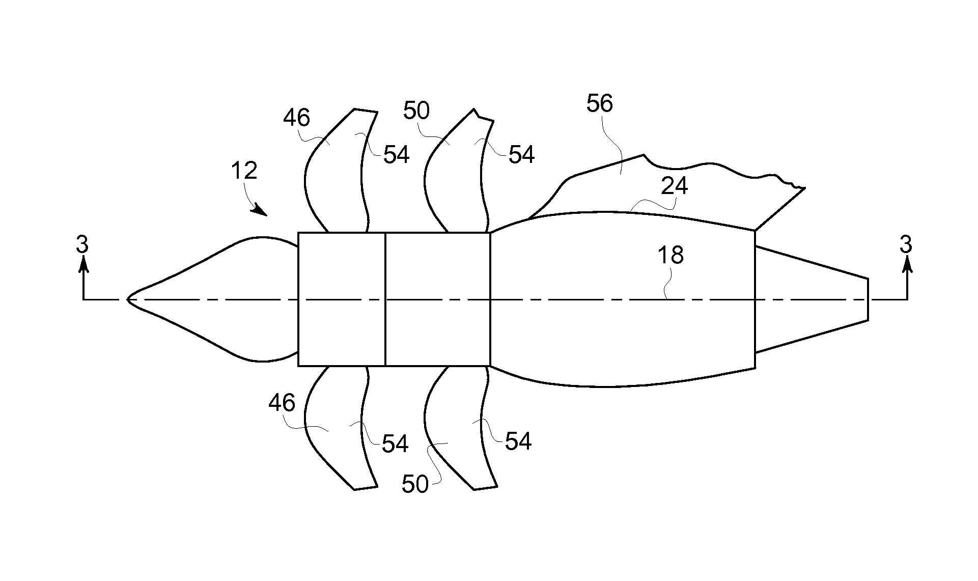
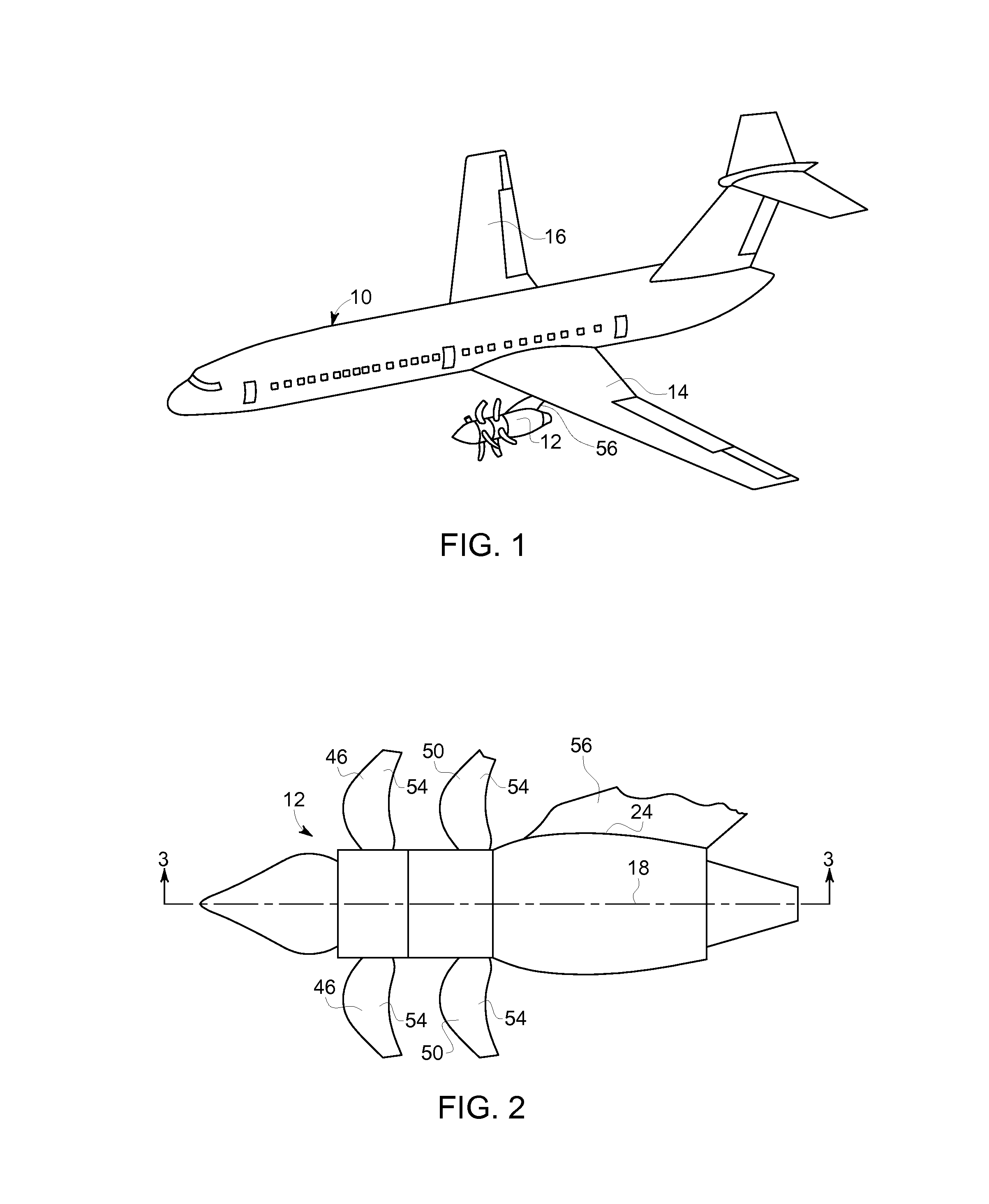
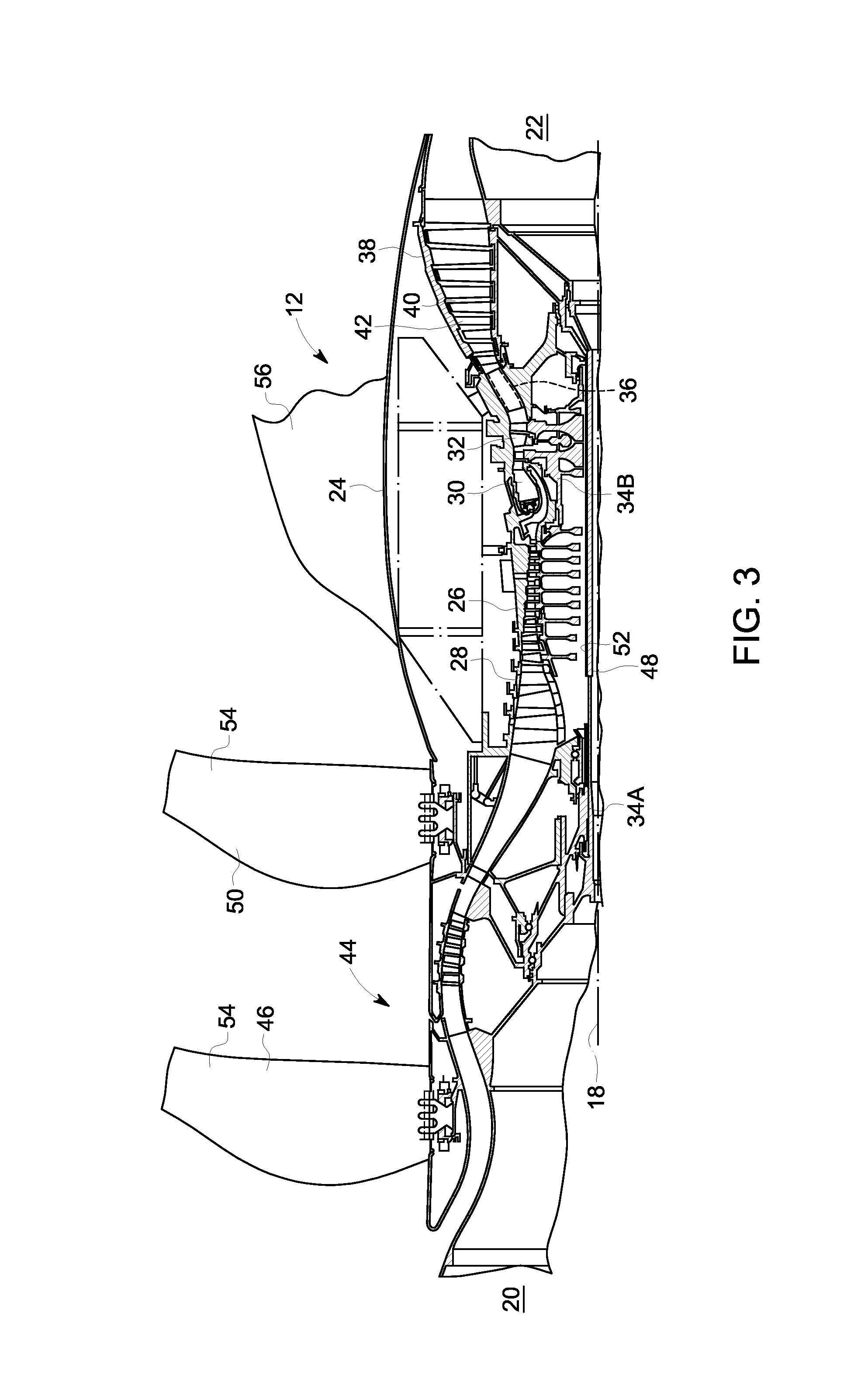
[0019]Generally provided are exemplary apparatus and methods for fabricating an airfoil such as, but not limited to, for use in a device incorporating aerodynamic surfaces, and more particularly for use in a rotary device, such as, but not limited to, an open rotor propulsion system. The embodiments described herein are not limiting, but rather are exemplary only. It should be understood that the exemplary apparatus and methods for fabricating an airfoil disclosed herein may apply to any type of airfoil or aerodynamic surface, such as, but not limited to, fan blades, rotor blades, ducted fan blades, unducted fan blades, turbine engine, wind turbines, aircraft wing high-lift systems and / or aircraft structures. More specifically, the exemplary apparatus and methods for fabricating an airfoil disclosed herein may apply to any airfoil, or aerodynamic surface, that is subject to impinging wakes and vortices generated upstream of the airfoil.

[0020]Although the embodiments described herein...


PUM

PropertyMeasurementUnit
pressureaaaaaaaaaa
chord lengthaaaaaaaaaa
lengthaaaaaaaaaa

Abstract

An airfoil, a fan assembly and an unducted contra-rotating fan engine include fabricating at least one airfoil including a suction and a pressure side coupled together at a leading and a trailing edge and extending therebetween. The airfoil includes a plurality of chord sections having a chord length. The airfoil including a tip profile defining a reducing slope extending from the leading edge at the tip portion along at least a portion of the chord length. The tip profile is configured to reduce the high unsteady pressure near the tip portion of the airfoil.

Description

STATEMENT REGARDING FEDERALLY SPONSORED RESEARCH OR DEVELOPMENT[0001]This invention was made with Government support under DTFAWA-10-C-00046 awarded by United States Department of Transportation Federal Aviation Administration. The Government has certain rights in this invention.BACKGROUND[0002]Embodiments presented herein relate generally to aerodynamic surfaces configured for noise reduction, and more specifically to configuration of a tip portion on an aerodynamic surface, such as an airfoil, for noise reduction.[0003]At least some known machines including aerodynamic surfaces such as, but not limited to, wind turbines, aircraft airframes, aircraft engines, gas turbine engines and steam turbine engines, include a plurality of stationary and / or rotating airfoils which are subject to impinging wakes and vortices generated from an upstream object, such as an upstream bladerow or an input unsteady airflow. The upstream generated wakes and vortices are channeled downstream where they ...

Claims


Application Information

Patent Timeline
Patent Type & Authority Patents(United States)
IPC IPC(8): F01D5/14B64C11/18F01D1/26B64D27/00
CPCB64C11/18F01D5/141B64D2027/005Y02T50/66Y02E10/722F01D1/26Y10T29/49336B64C11/48F01D5/20F04D19/024F04D29/681F05D2240/307F04D29/164F04D29/324Y02E10/72F05D2250/712F05D2220/36Y02T50/60F01D5/145
Inventor WOOD, TREVOR HOWARD
Owner GENERAL ELECTRIC CO
Why Eureka
Try Eureka