
Winding synchronous machine having a moving object including an inverter circuit, and method for controlling same

a synchronous machine and moving object technology, applied in the direction of electric devices, battery/cell propulsion, transportation and packaging, etc., can solve the problems of increasing costs, hard to change in real, increasing costs, etc., and achieve the effect of reliably controlling a magnetic field current and increasing costs

Active Publication Date: 2015-08-18
SEOUL NAT UNIV R&DB FOUND
View PDF15 Cites 2 Cited by
  • Summary
  • Abstract
  • Description
  • Claims
  • Application Information

AI Technical Summary

Benefits of technology

The present invention solves problems related to rare earth-based permanent magnets, such as supply and demand, material procurement, and increased cost. It also improves the control of magnetic field current and provides a wound-rotor type synchronous machine that does not require a separate electric power. The technical effects of this invention are reliable control of magnetic field current and improved efficiency of rare earth-based permanent magnets usage in synchronous machines.

Problems solved by technology

A rare earth-based permanent magnet synchronous machine is famous for an enhanced torque and output density and a high efficiency, but it has a disadvantage in the middle of operations in a flux weakening or field weakening section since it is hard to change in real time the magnetic flux of a rare earth-based permanent magnet.
Despite the above mentioned disadvantage, the use of the permanent synchronous machines is growing in various application fields such as vehicles, wind power, etc.
Since a limited number of countries is gifted to exclusively produce the rare earth materials which are used in the rare earth-based permanent magnets, it is hard to obtain enough rare earth materials due to the increasing use of such rare earth materials, which problems consequently cause an increase in costs.
Since an electric vehicle, a hybrid vehicle and a permanent magnet-based wind power generator continue to increase, it is expected that the rare earth-based permanent magnets necessarily adapted in the permanent magnet motor and the generator which are key elements in generating the driving forces for the system become harder and harder to obtain and use, so many researches for developing substitutable materials are in process.
The magnetic field current may be supplied in the above mentioned way to the rotor, but a current pulsation components contained in the magnetic field current and the stator current may decrease the efficiency of all parts of the synchronous machine and may cause torque pulsation, which results in the decreased performance of the whole systems.

Method used


Image

  • Winding synchronous machine having a moving object including an inverter circuit, and method for controlling same
  • Winding synchronous machine having a moving object including an inverter circuit, and method for controlling same
  • Winding synchronous machine having a moving object including an inverter circuit, and method for controlling same

Examples


Embodiment Construction

[0048]The preferred embodiments of the present invention will be described with reference to the accompanying drawings. In the middle of the descriptions of the present invention, if a known function or construction is judged to make unclear the subject matters of the claimed invention, the descriptions on such known function or construction will be omitted. The terms used throughout the descriptions and claims are well defined in consideration of the functions of the present invention and may be interpreted differently from the operator's intension or practices. It is preferred that the terms should be defined in accordance with the contents disclosed herein.

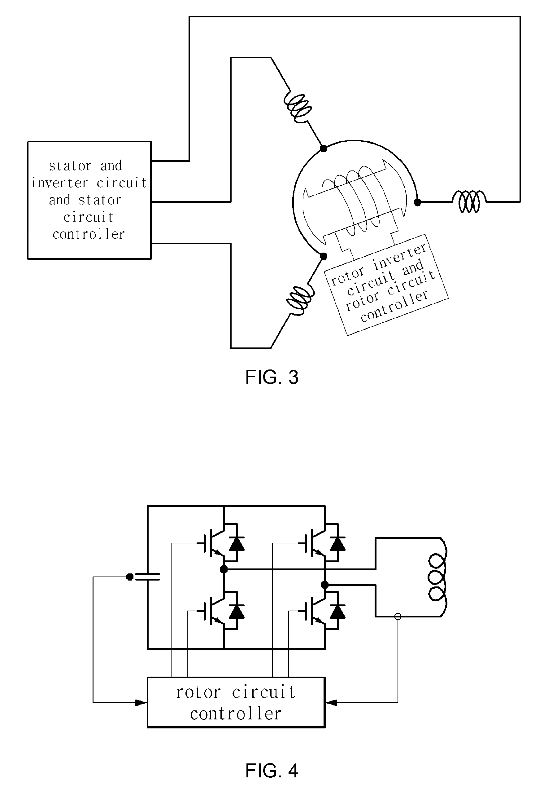
[0049]FIG. 3 is a schematic view illustrating a wound-rotor type synchronous machine equipped with an inverter circuit-integrated rotor according to the present invention. The present invention will be described focusing on the rotary devices, but it is obvious that the wound-rotor type linear devices equipped with an inverter ...


PUM


Abstract

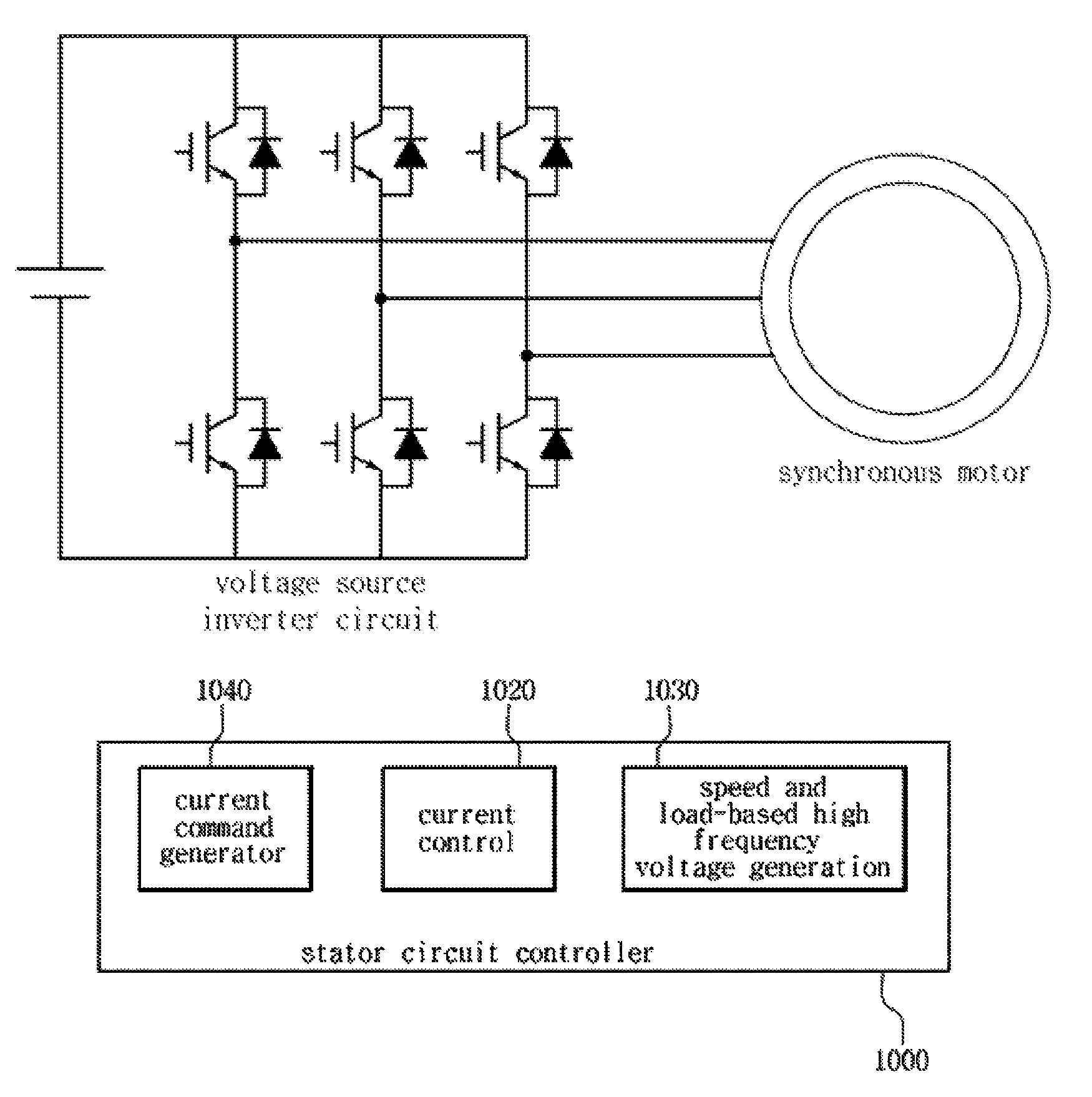
A winding synchronous machine having a moving object including an inverter circuit comprises: a moving-object inverter circuit connected to the moving object of the winding synchronous machine; and a moving-object circuit control device connected to the moving-object inverter circuit so as to control the moving-object inverter circuit. The moving-object circuit control device may comprise: a stator inverter voltage estimator estimating a high-frequency voltage of a stator inverter circuit; a field current reference generator generating a field current reference of the moving object; and an energy storage device voltage controller generating a current reference tracking a DC-link energy storage device voltage of the moving object. Problems associated with using a rare-earth permanent magnet can be thereby overcome, and a winding synchronous machine including an excitation circuit in which ripples almost never occur can be implemented without using an extra power source.

Description

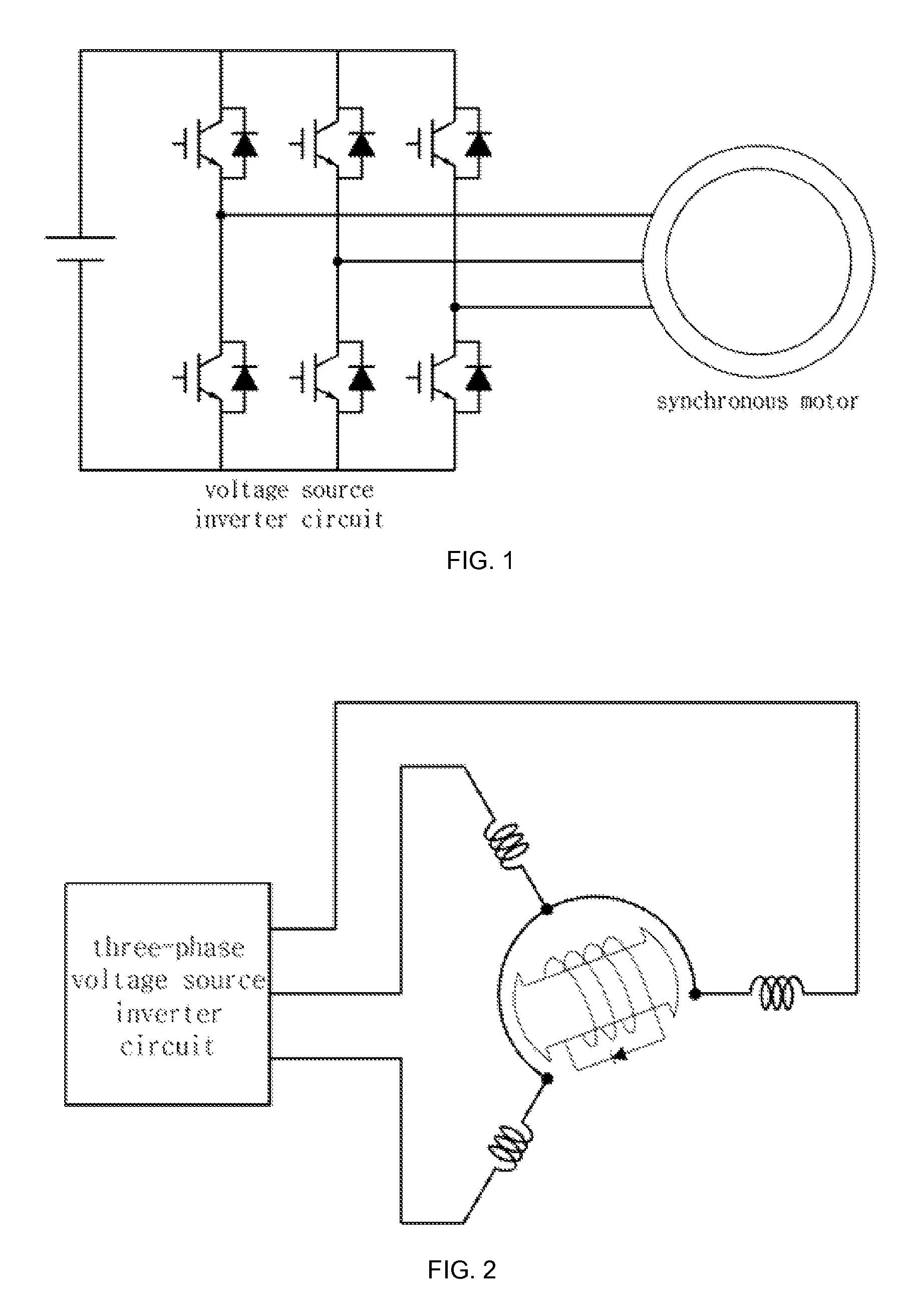
TECHNICAL FIELD[0001]The present invention relates to a wound-rotor type synchronous motor or a wound-rotor type synchronous machine equipped with a generator, and in particular to a wound-rotor type synchronous machine equipped with an inverter-integrated rotor or mover.BACKGROUND ART[0002]Thanks to a great advance in an electric power and electronic technology, the use of an inverter is significantly increasing in a motor / generator application field. As best seen in FIG. 1, a Voltage Source Inverter (VSI) is generally used in an electric and machine driving system. Various types of electric and machine systems may be applied to an inverter application; however an induction motor / generator or a synchronous machine is widely used for industrial applications because it has a higher quality. A rare earth-based permanent magnet synchronous machine is famous for an enhanced torque and output density and a high efficiency, but it has a disadvantage in the middle of operations in a flux w...

Claims


Application Information

Patent Timeline
Patent Type & Authority Patents(United States)
IPC IPC(8): H02P1/46H02P25/02B60L11/18H02P27/14H02K11/00
CPCH02P25/026B60L11/1803H02K11/0073H02P25/021H02P27/14B60L2220/14Y02T10/642Y02T10/7005B60L15/007B60L15/20B60L2220/16B60L2220/50B60L2240/421B60L2240/427B60L2240/527B60L2260/44B60L50/51H02K11/33H02P25/024H02P25/03Y02T10/64Y02T10/70Y02T10/72H02P21/00H02P27/04
Inventor SUL, SEUNG-KIHA, JUNG-IKJUNG, EUNSOO
Owner SEOUL NAT UNIV R&DB FOUND
Learn More