
Gasification reactor

a gasification reactor and gasification chamber technology, applied in the direction of gasification of granular/pulverulent flues, gasification mechanical details, combustible gas production, etc., can solve the problems of early failure of the seal, induced loads on the gasifier walls, etc., to reduce thermal loads, reduce thermal loads, and prevent possible viscosity changes caused by concentration of dispersed particles

Active Publication Date: 2015-08-25
AIR PROD & CHEM INC
View PDF8 Cites 0 Cited by
  • Summary
  • Abstract
  • Description
  • Claims
  • Application Information

AI Technical Summary

Benefits of technology

This patent is about a sealing arrangement for a gasifier, which helps to prevent leaks and reduce pressure fluctuations. The arrangement includes an upper seal and a lower seal, with the lower seal designed to handle high-frequency pressure fluctuations. The lower seal is more flexible than the upper seal and is designed to cope with changes in the load pattern. The hydraulic lock in the system helps to flush the system and prevent corrosion and viscosity changes. It also includes an overflow that cools the gasifier wall and prevents thermal loads. Overall, this sealing arrangement improves the reliability and efficiency of the gasifier.

Problems solved by technology

These gasifier walls are subjected to loads induced by the high operational pressures within the gasifier.
The accumulated loading pattern can lead to early failure of the seal.

Method used


Image

  • Gasification reactor
  • Gasification reactor
  • Gasification reactor

Examples


Embodiment Construction

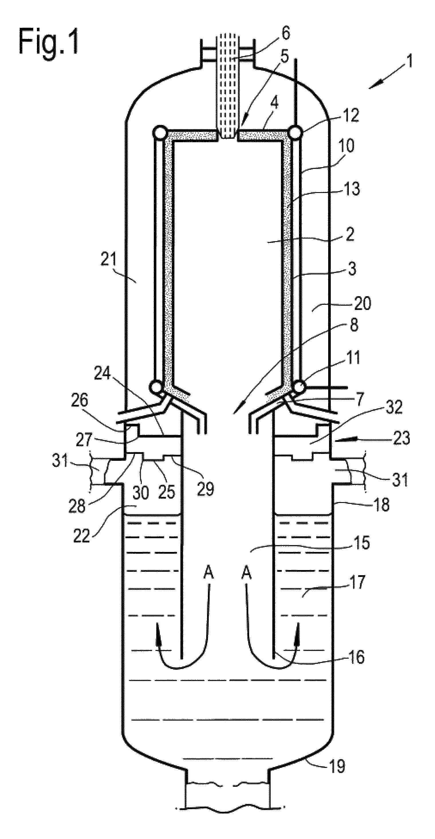
[0026]FIG. 1 shows a gasification reactor 1 comprising a gasifier 2 with a cylindrical gasifier wall 3, a closed top end 4 having a central passage opening 5 for passage of a burner 6, and a tapering lower end 7 narrowing down to a gas discharge opening 8. Alternatively, or additionally, the gasification reactor can have one or more burners entering the gasifier from a lateral position. The gasifier wall 3 is built of parallel vertical coolant lines 10 interconnected to form a gastight structure. At the lower end of the coolant lines 10 a coolant medium is supplied via a circular distributor line 11. The coolant medium is discharged via a circular header line 12 on top of the coolant lines 10. In this particular embodiment, the inner surface of the gasifier wall 3 is provided with a refractory liner 13.

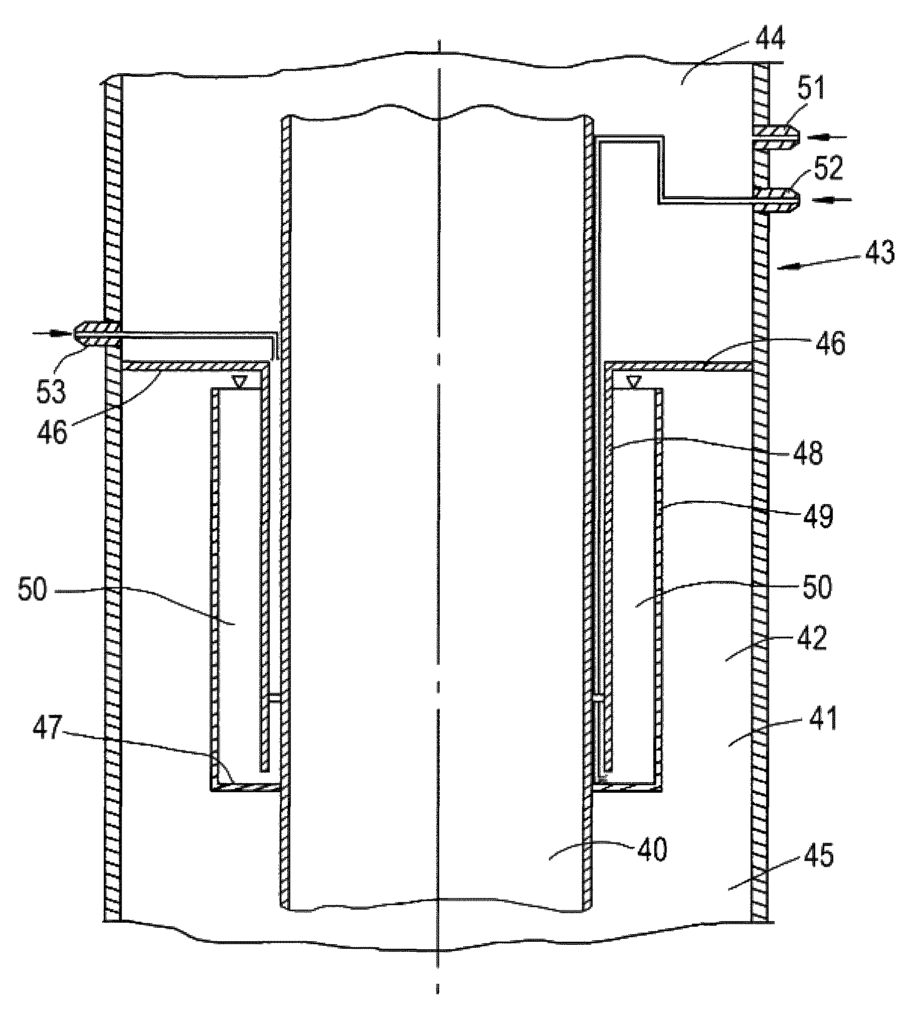
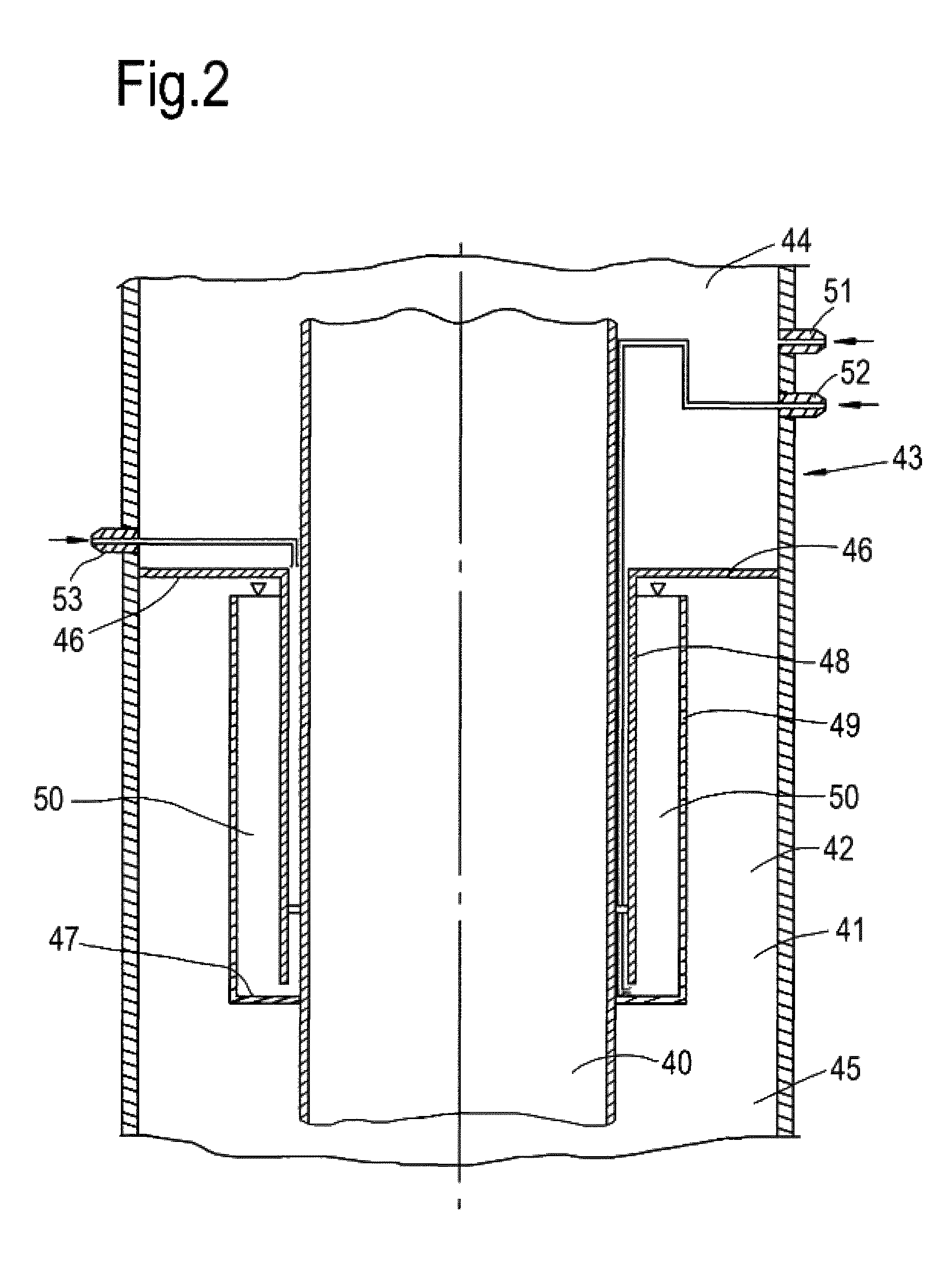
[0027]A cylindrical discharge channel or dip tube 15 is arranged in line with the discharge opening 8. The dip tube 15 has a lower end 16 extending into a coolant reservoir 17, such a...


PUM

PropertyMeasurementUnit
pressureaaaaaaaaaa
pressureaaaaaaaaaa
pressureaaaaaaaaaa

Abstract

A gasification reactor including a gasifier having a tubular gastight wall with a discharge channel or dip tube at its lower end leading into a lower slag collection bath. The gastight wall and the slag collection bath are arranged within a pressure vessel. An annular space between the pressure vessel and the gasifier with the discharge channel is separated in a high pressure top section and a low pressure lower section by a sealing arrangement having a damper. The damper can for instance be a hydraulic lock, or a lower seal at a distance below an upper seal.

Description

PRIORITY CLAIM[0001]The present application claims priority from PCT / EP2012 / 051184, filed 26 Jan. 2012, which claims priority from European application 11152587.9, filed 28 Jan. 2011, which is incorporated herein by reference.BACKGROUND OF THE INVENTION[0002]The present invention relates to a gasification reactor comprising a gasifier in a tubular gastight wall with a lower end opening into an aqueous slag collection bath, wherein the gastight wall is arranged within a pressure vessel.[0003]Gasification reactors can for instance be used for the production of synthesis gas by partial combustion of a carbonaceous feed, such as pulverized coal, oil, biomass, gas or any other type of carbonaceous feed. Some gasification reactor types only have a discharge opening at their lower end for discharging syngas via the aqueous slag collection bath via a discharge, often referred to as dip tube. Due to the pressure build-up in the gasifier freshly produced synthesis gas is forced to flow down t...

Claims


Application Information

Patent Timeline
Patent Type & Authority Patents(United States)
IPC IPC(8): C10J3/76C10J3/48C10J3/78
CPCC10J3/76C10J3/485C10J3/78C10J2200/09C10J3/48
Inventor KARZEL, PAUL CHRISTIANSCHMITZ-GOEB, MANFRED HEINRICH
Owner AIR PROD & CHEM INC
Learn More