Enhanced graphical flight planning for a flight management system

a flight management system and graphical flight planning technology, applied in the field of aircraft avionics systems, can solve the problems of inability to accurately predict the flight of the aircraft, so as to eliminate the head-down time, and reduce the workload of the pilot

Active Publication Date: 2015-08-25
ROCKWELL COLLINS INC
View PDF8 Cites 18 Cited by
  • Summary
  • Abstract
  • Description
  • Claims
  • Application Information

AI Technical Summary

Benefits of technology

[0017]In one broad aspect, the present invention is a system for performing an expedited graphical flight plan edit for an aircraft. The system comprises a flight management system (FMS) for an aircraft; a multi-function display (MFD) operatively connected to the FMS; and, a cursor control device (CCD) operatively connected to the MFD. The CCD is configured to interact with the MFD as the user interface to the FMS for performing shortcut graphical flight plan edits. Expedited graphical flight planning operations include—Expedited Direct To, Expedited Vertical Direct To, Vectors to Final, and Sequence Vectors. Pilot actions performed on the MFD accomplishes the flight plan edit as compared to several pilot actions when using the CDU. By combining the operations with the other related edit operations graphically, pilot workload is reduced as it eliminates heads-down time and abbreviates the number of actions required to complete the flight plan modification
[0018]In another broad aspect, the present invention is embodied as a system for performing a waypoint vertical direct to graphical flight plan edit for an aircraft. In addition to the elements noted above, an analog input control (AIC) device is used for controlling a numerical value. The AIC device is operatively connected to the display so that the CCD and the AIC device are so arranged and configured to interact with the MFD as the user interface to the FMS for performing a waypoint vertical direct to graphical flight plan edit. The CCD presents a task menu including a virtual task button on the MFD. The virtual task button includes a button window having a display readout which is modifiable by the user. After entry / adjustment of the numerical value is finished, selection of the virtual button via the CCD not only accepts the value but also causes the flight plan edit to be sent from the MFD to the FMS for processing. This graphical flight planning task using the CCD on the electronic map results in a single combined edit provided to the FMS rather than using the CDU which requires separate uncombined steps to perform the same operation. By combining the operations with the other related edit operations graphically, pilot workload is reduced as it eliminates heads-down time and abbreviates the number of actions required to complete the flight plan modification.
[0019]In another broad aspect, the system performs a parallel offset graphical flight plan edit for an aircraft. The CCD presents a task menu comprising a virtual button on the MFD which is replaced by a course line, a display dynamic readout, and a ghost aircraft. Manipulation of the AIC device provides adjustment of a value of the display dynamic readout and commensurate dynamic positioning of the display dynamic readout, the course line and the ghost aircraft. Completion of an entry using the CCD completes the parallel offset adjustment. The pilot's attention can be undivided and focused on the electronic map since the data entry and graphical results are displayed in the same location on the same device. Because of this fact and that this embodiment also eliminates the trial and error input value adjustment situation, pilot workload is minimized for this type of FMS flight plan modification.
[0020]In another broad aspect, the system performs an airway insertion graphical flight plan edit for an aircraft. The CCD presents a waypoint task menu comprising a virtual button on the MFD which, upon selection of an airway task the waypoint task menu is replaced by an airways dialogue box. The airways dialogue box comprises a circle denoted by a selected waypoint. The circle has a plurality of optional airways extending therefrom. Manipulation of the AIC device provides graphical highlighting of a desired airway. Selection of an identifier region from the airway exit identifier list results in the appearance of a proposed airway flight plan edit on the display. Completion of an entry using the CCD completes the flight plan modification. This avoids requiring the pilot to manually type the alphanumeric name using the keyboard, eliminates any possibility for typographical errors and all available identifiers are made visible without requiring memorization or searching on a chart.
[0021]In another broad aspect, the system performs an instrument procedure insertion / change graphical flight plan edit for an aircraft. The CCD presents an airport task menu comprising a virtual button on the MFD which, upon selection of an instrument procedure task the airport task menu is replaced by an instrument procedures dialogue box. The instrument procedures dialogue box displays a plurality of lists of available instrument procedures for the selected airport. Manipulation of the CCD provides graphical highlighting of the desired instrument procedure. Selection of the desired instrument procedure using the CCD results in the flight plan to be modified to include the selected instrument procedure, the selected instrument procedure highlighted in the list, the selected instrument procedure displayed in a readout window above the list, the display lists to remain in view after the selection is made and the appearance of the selected instrument procedure on the display. In cases where there is both an active procedure and a newly selected procedure, both are highlighted differently in the list. This embodiment has two advantages since all available instrument procedures remain visible. It avoids memorization of the active instrument procedure selections which are separate from any new selections currently made and also reduces pilot workload in cases where changes to the instrument procedure selections are required.
[0022]In another broad aspect, the system performs a graphical definition of a navigation reference fix for an aircraft. The CCD presents a task menu comprising a virtual button on the MFD which, upon selection of a fix task the task menu is replaced by a fix dialogue box. The fix dialogue box allows for entry and / or adjustment of navigation reference fix input data which can be observed directly on an electronic map. Manipulation of the CCD selects the desired fix input parameter for adjustment. Manipulation of the AIC provides adjustment of the numerical value while graphical navigation reference fix symbology is dynamically positioned on the electronic map which correlates to the numerical value displayed in the fix dialogue box. After entry / adjustment of the value is finished, selection is made via the CCD control which causes the navigation reference fix value to be sent from the MFD to the FMS for further processing. The pilot's attention can be undivided and focused on the electronic map since the data entry and graphical results are displayed in the same location on the same device. This embodiment also eliminates the trial and error input data adjustment situation, thereby reducing pilot workload for this type of FMS operation.

Problems solved by technology

Flight management systems (FMS′) for aircraft, which use a Control Display Unit (CDU) as the only pilot user interface, are inherently inefficient in some cases.
These inefficiencies are manifested in terms of the amount of time, the number of steps and / or the entry method the pilot is forced to use to input / adjust flight plan parameters.
In addition, the CDU user interface is limited to entry of discrete alphanumeric values using an alphanumeric keypad.
Because of these factors, using the CDU as the pilot interface for modifying flight plans sometimes has the disadvantage of high pilot workload for the following reasons:
The CDU requires significant amounts of heads-down time due to complexity of operation.
In addition, awareness of the active selection is lost since the display lists are context sensitive and updated to reflect the current selection only.
Entry of the desired value into the CDU, especially when it may need adjustment, is by trial and error.
The embodiments of the prior art reduce certain aspects of the high pilot workload and inefficiencies associated with an FMS CDU user interface but are still lacking in many areas.

Method used


Image

  • Enhanced graphical flight planning for a flight management system
  • Enhanced graphical flight planning for a flight management system
  • Enhanced graphical flight planning for a flight management system

Examples


Embodiment Construction

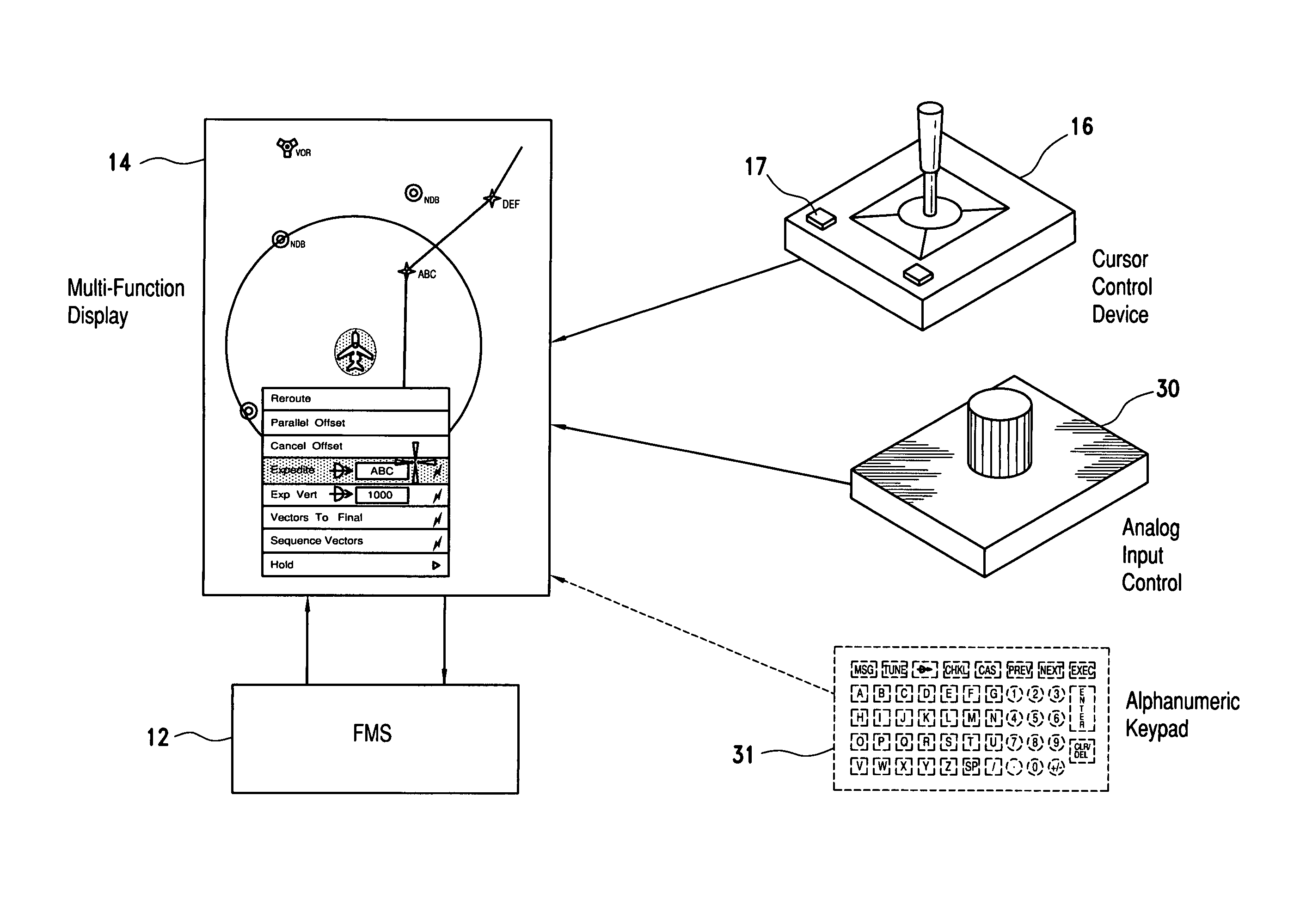
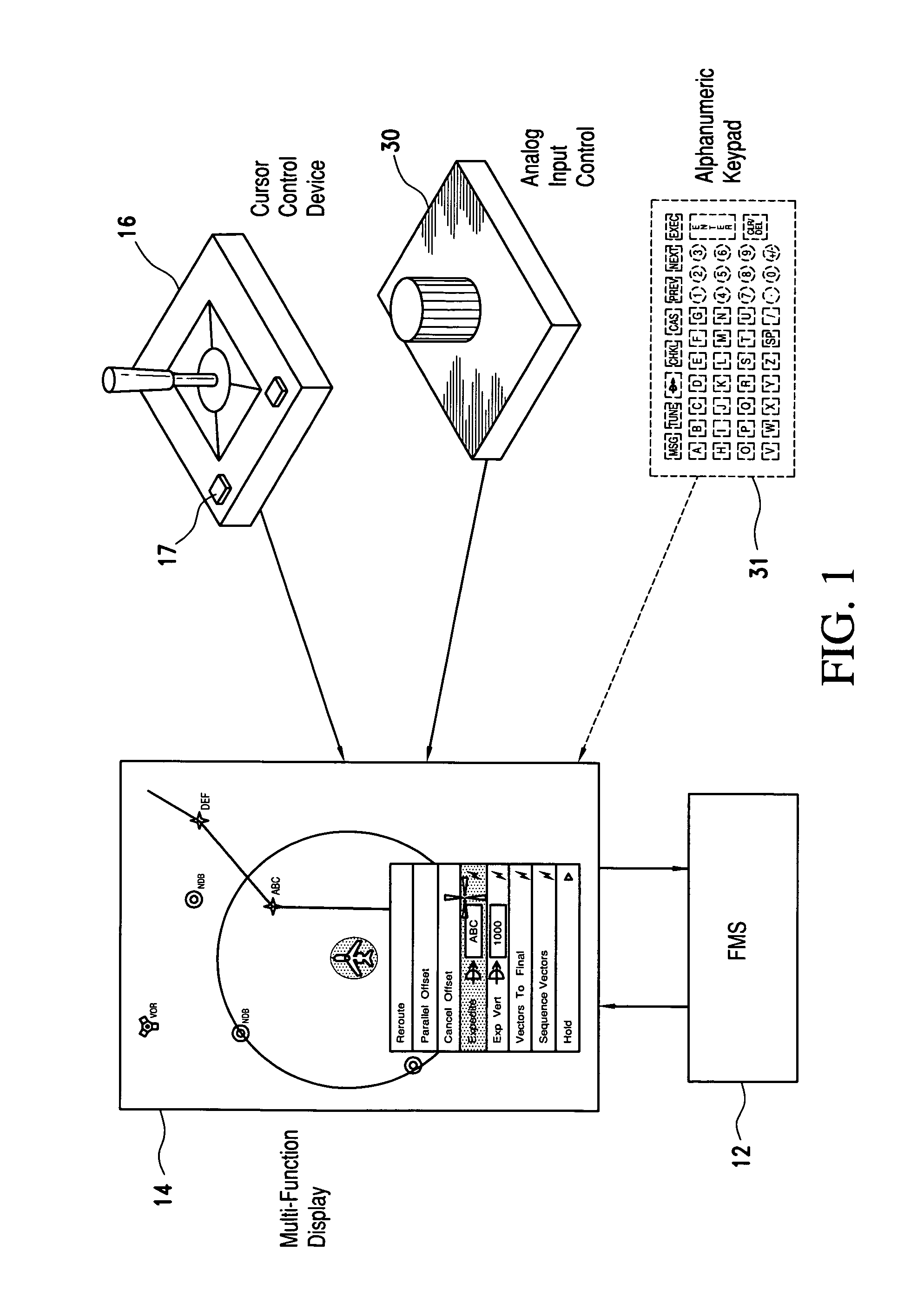
[0034]Referring now to the drawings and the characters of reference marked thereon, FIG. 1 illustrates a system for performing an expedited graphical flight plan edit for an aircraft, designated generally as 10. The system 10 includes a flight management system (FMS) 12 which may be a type that is typical in this field such as that manufactured by present assignee, Rockwell Collins, Inc. A multi-function display (MFD) 14 is operatively connected to the FMS. The MFD 14 is also of a type known in this field. The MFD represents any electronic flight display which is capable of displaying an electronic map format that includes an FMS generated flight plan. A cursor control device (CCD) 16 is connected to the MFD 14. It may be, for example, a joystick, trackball, touch pad, or mouse. Cursor control could alternatively be provided via arrow keys on an alphanumeric keypad. The display format presented on the MFD is utilized for performing a desired edit to a flight plan. The CCD 16 prefera...


PUM


Abstract

The present invention provides systems, apparatus and means to perform various FMS flight plan edits and definition of navigation reference fixes using interactive graphical representations displayed on an MFD rather than a text-based CDU. In two of the embodiments of the present invention, means are provided where minimal pilot actions, i.e., shortcuts, (which may also include entry/adjustment of a numerical value) are performed on an electronic display that accomplish particular flight plan edits as compared to several pilot actions when using a CDU to perform the same edits. In another embodiment of the present invention, a means is provided where the data entry method is graphical in nature rather than alphanumeric text for inserting an airway into a flight plan. The alphanumeric identifiers are represented as graphical objects which are selectable. In yet another embodiment, the present invention teaches a means for a flight plan modification consisting of the entry or bidirectional adjustment of a parallel offset value directly on an electronic map. In another embodiment, the present invention includes the display of a dialog box showing interactive lists of the available instrument procedures for the selected airport which is displayed on an electronic map. The display lists remain in view after selections are made with the active selection and new selection highlighted differently in the list. In another embodiment of the present invention, a means is provided to allow entry/adjustment of navigation reference fix input data directly on the electronic map. Graphical navigation reference fix symbology is dynamically positioned on the electronic map while the input data value is being adjusted.

Description

BACKGROUND OF THE INVENTION[0001]1. Field of the Invention[0002]The present invention relates generally to aircraft avionics systems, and more particularly to a system for optimizing the pilot interface with the flight management system (FMS).[0003]2. Description of the Related Art[0004]Flight management systems (FMS′) for aircraft, which use a Control Display Unit (CDU) as the only pilot user interface, are inherently inefficient in some cases. These inefficiencies are manifested in terms of the amount of time, the number of steps and / or the entry method the pilot is forced to use to input / adjust flight plan parameters. This situation is further compounded when the input is made via the CDU while the displayed results are observed on the electronic map of a Multi-Function Display (MFD).[0005]This is due in part to the distribution of the controls located on the CDU that are a combination of both dedicated hard keys and line select soft keys. In addition, the CDU user interface is l...

Claims


Application Information

Patent Timeline
Patent Type & Authority Patents(United States)
IPC IPC(8): G05D1/00G01C23/00
CPCG01C23/00G01C23/005G01C5/005G08G5/025G08G5/0034G08G5/0021
Inventor OWEN, GARY L.LEHMAN, MAUREEN A.ESPENES, MICHAEL G.BAUER, MICHAEL K.KANKELFITZ, KEITH E.SOLAR, RICHARD S.
Owner ROCKWELL COLLINS INC
Why Eureka
Try Eureka