Method and system for determining the load on an element of the drive system of a plunger in a baler

a technology of drive system and baler, which is applied in baling, agriculture tools and machines, agriculture, etc., can solve the problems of high cost, complex set-up with careful calibration, and rapid ageing of baler components,

Active Publication Date: 2015-09-01
CNH BELGIUM +1
View PDF8 Cites 2 Cited by
  • Summary
  • Abstract
  • Description
  • Claims
  • Application Information

AI Technical Summary

Benefits of technology

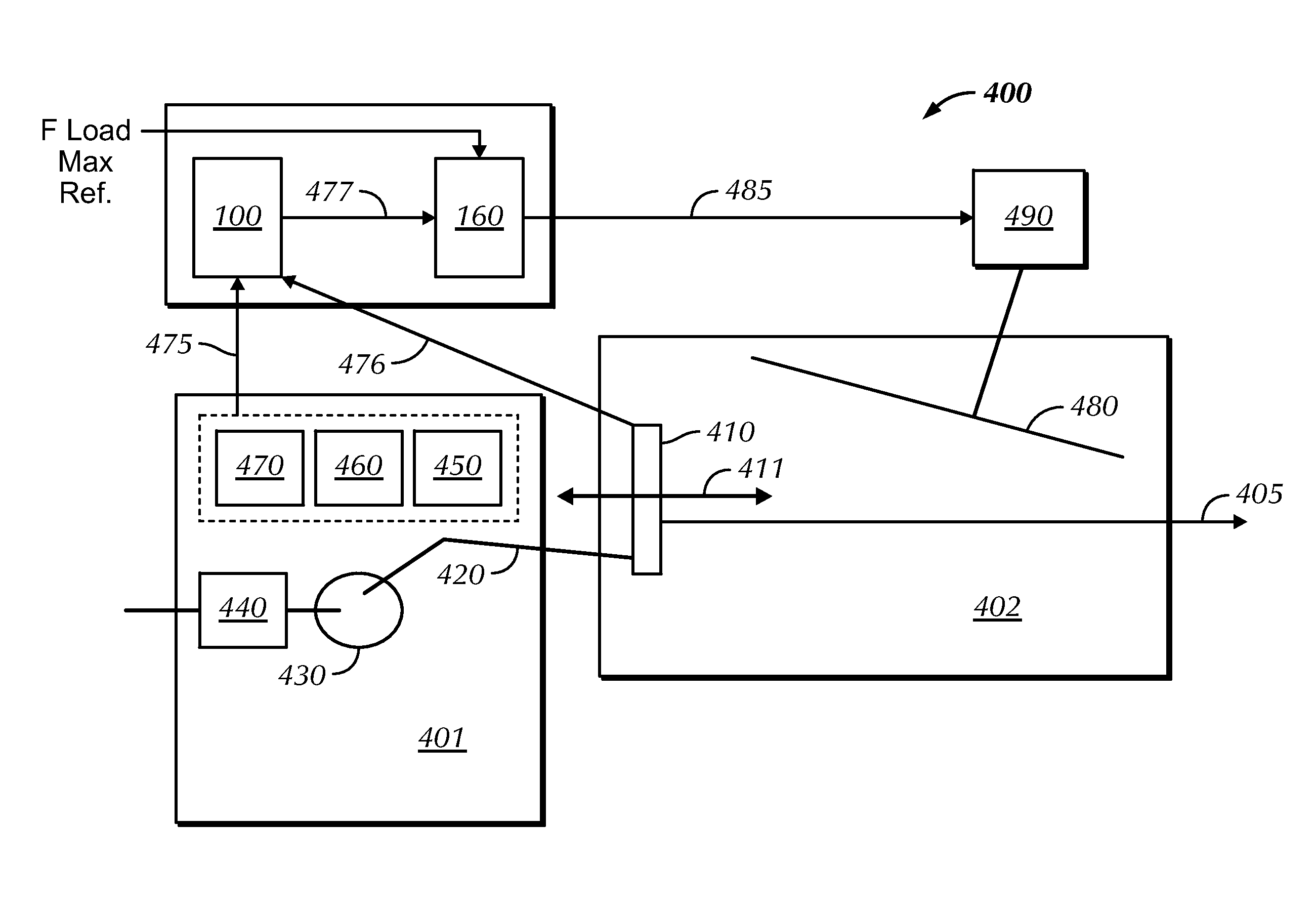
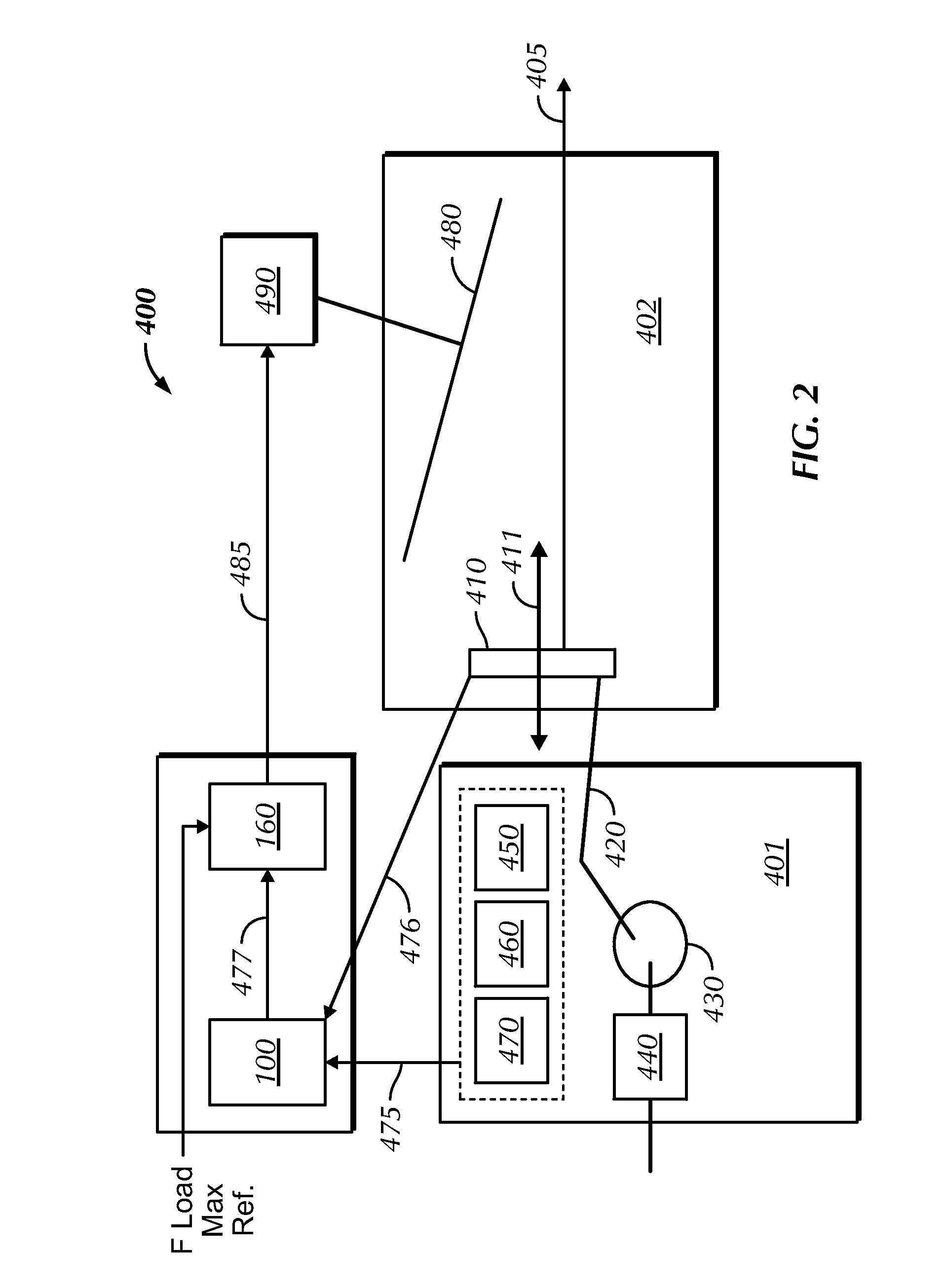
[0006]It is an object of embodiments of the present invention to provide a safety system and method for protecting the gear box of an agricultural baler against overloads.
[0014]In a further embodiment, a display is provided for displaying the value representative of or an estimate of the load on one or more elements of a drive system to the baler operator. Such display may aid an operator of the baler to get maximum productivity with his machine, without going over the limits and destroying or fastly ageing components thereof. Such display may be, but does not need to be, provided in a tractor towing the baler.
[0026]It is an advantage of embodiments of the present invention that methods and systems are provided which may be used in balers for harvesting crop, more in particular methods and systems for determining the load on one or more elements of the drive system of the plunger. Such methods and systems may be used for controlling such balers. The methods and systems provided according to embodiments of the present invention are simple, cheap and robust.

Problems solved by technology

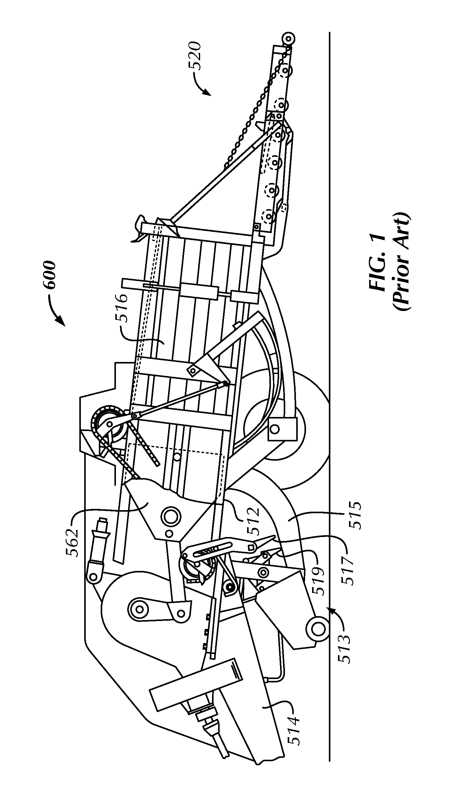
The operation of such high density baler results in high loads on the elements of the baler such as the plunger, its drive elements or other elements, which might result in break-down or rapid ageing if the baler is not operated properly.
While measuring by sensors and controlled operation based thereon is used in the art, e.g. on the baler chamber, it is known in the field that measuring of loads by load sensors and strain gauges, as for example presented in EP0655190, is expensive and / or requires a complex set-up with careful calibration because of the high loads involved.
Furthermore, it has been noticed that, despite the load measurements in EP0655190, gear box shear bolts still break, indicating that unexpected large loads apply to the gear box.

Method used


Image

  • Method and system for determining the load on an element of the drive system of a plunger in a baler
  • Method and system for determining the load on an element of the drive system of a plunger in a baler
  • Method and system for determining the load on an element of the drive system of a plunger in a baler

Examples


Embodiment Construction

[0040]The present invention will be described with respect to particular embodiments and with reference to certain drawings but the invention is not limited thereto but only by the claims.

[0041]It is to be noticed that the term “comprising”, used in the claims, should not be interpreted as being restricted to the means listed thereafter; it does not exclude other elements or steps. It is thus to be interpreted as specifying the presence of the stated features, integers, steps or components as referred to, but does not preclude the presence or addition of one or more other features, integers, steps or components, or groups thereof. Thus, the scope of the expression “a device comprising means A and B” should not be limited to devices consisting only of components A and B. It means that with respect to the present invention, the only relevant components of the device are A and B.

[0042]Reference throughout this specification to “one embodiment” or “an embodiment” means that a particular...


PUM


Abstract

System and method of determining the load on an element of the drive system of a plunger of an agricultural baler, and to use thereof for controlling such balers. A value representative of an estimate of the load on an element of the drive system of the plunger is determined, based on combining an obtained value representative of the load on the plunger with obtained position information of the drive element relative to the plunger.

Description

[0001]This application is the US National Stage filing of International Application Serial No. PCT / EP2013 / 055196 filed on Mar. 14, 2013 which claims priority to Belgian Application BE2012 / 0169 filed Mar. 14, 2012, each of which is incorporated herein by reference in its entirety.FIELD OF THE INVENTION[0002]The present invention relates to methods and systems used in balers for harvesting crop, more in particular to methods and systems for determining the load on an element of the drive system of a plunger in a baler and use of such methods and systems for controlling such balers.BACKGROUND OF THE INVENTION[0003]An agricultural baler is a trailed machine, typically towed behind an agricultural vehicle such as a tractor, used in agriculture for the purpose of forming bales of agricultural crop materials, such as straw, hay, silage or other biomass, produced during a harvesting or mowing operation. A baler typically comprises an infeed through which biomass is introduced into a bale-fo...

Claims


Application Information

Patent Timeline
Patent Type & Authority Patents(United States)
IPC IPC(8): A01F15/04A01F15/08B30B9/30
CPCA01F15/04A01F15/08A01F15/0825A01F15/0841B30B9/3007
Inventor BONTE, XAVIER G. J. M.TALLIR, FREDERIK
Owner CNH BELGIUM
Why Eureka
Try Eureka