
Method for manufacturing composite metal alloy and method for manufacturing article from composite metal

a technology of composite metal and manufacturing method, which is applied in the direction of manufacturing tools, foundry patterns, moulding apparatus, etc., can solve the problems of scattering, and achieve the effects of increasing the degree of latitude in production, enhancing mechanical and thermal characteristics of the resulting article formed from composite metal, and high wettability

Inactive Publication Date: 2015-09-01
NISSEI PLASTIC IND CO LTD
View PDF6 Cites 2 Cited by
  • Summary
  • Abstract
  • Description
  • Claims
  • Application Information

AI Technical Summary

Benefits of technology

[0012]An object of the present invention is to provide a manufacturing method that can reduce the kneading time performed when a reinforcing material is added.

Problems solved by technology

As long as a powdered mixture is used, scattering will be a problem.

Method used


Image

  • Method for manufacturing composite metal alloy and method for manufacturing article from composite metal
  • Method for manufacturing composite metal alloy and method for manufacturing article from composite metal
  • Method for manufacturing composite metal alloy and method for manufacturing article from composite metal

Examples


Embodiment Construction

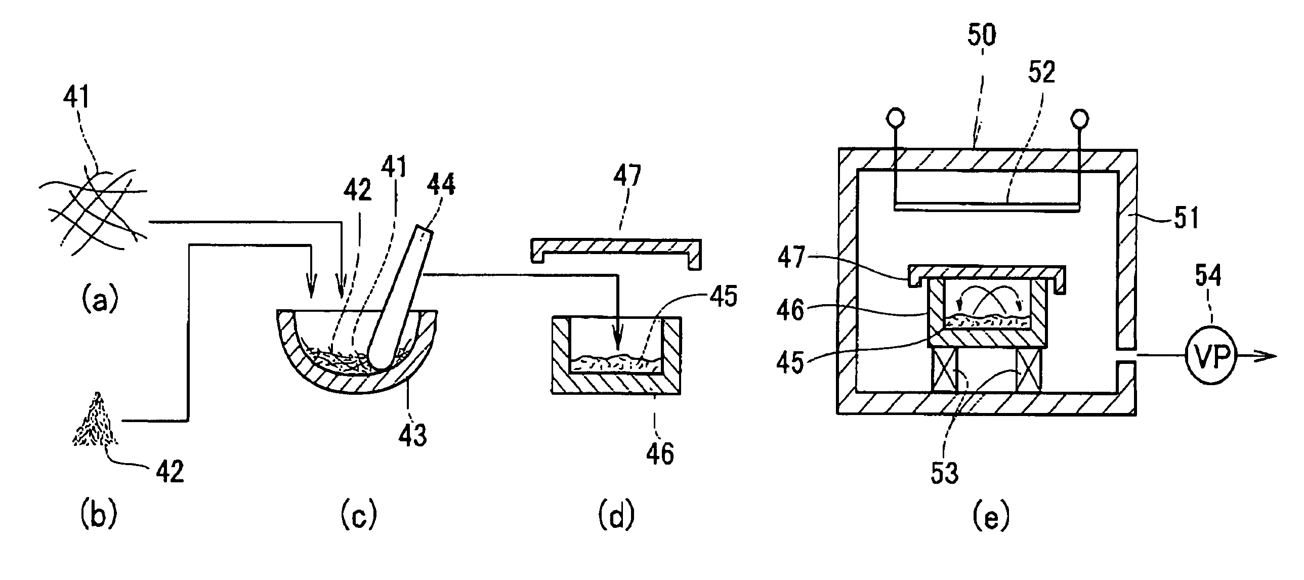
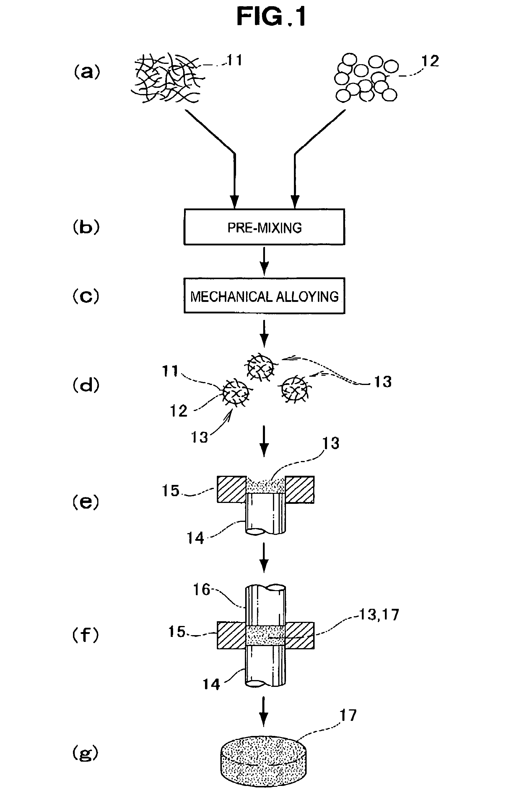
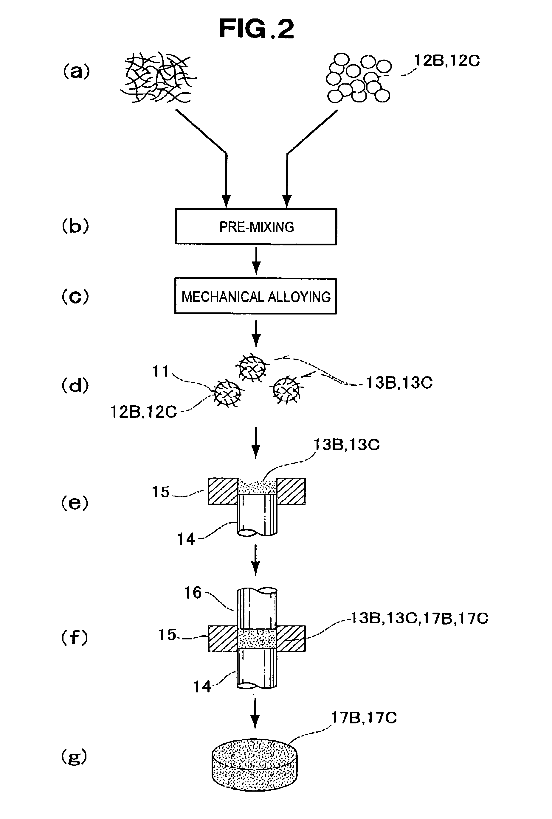
[0032]Reference is now made to FIGS. 1 to 3 showing one embodiment of the present invention. The metal alloy may be of any type provided that the metal alloy of the present invention is an Mg alloy or an Al alloy. ASTM AZ91D (corresponding to die-cast magnesium alloy JIS H 5303 MDC1D) is cited in the embodiment described below as an example of one of many candidate alloys. The chemical composition of MDC1D as stipulated by JIS is as shown in Table 1.

[0033]

TABLE 1SymbolAlMnZnSiCuNiFeOtherMgMDCID8.3-9.70.15-0.500.35-1.0≦0.10≦0.03≦0.002≦0.005≦0.02Bal.

[0034]MDC1D is a magnesium alloy made from about 9 mass % of Al, 0.5 mass % or less of Mn, and 1.0 mass % or less of Zn as alloying materials; and the remaining approximately 90 mass % of Mg as a base material.

[0035]Described below is a method for manufacturing a composite metal alloy having a material that is about 90 mass % Mg (base material); about 9 mass % of Al, 0.5 mass % or less of Mn, and 1.0 mass % of Zn as alloying materials; and...


PUM

PropertyMeasurementUnit
particle diameteraaaaaaaaaa
grain sizeaaaaaaaaaa
diameteraaaaaaaaaa

Abstract

A method for manufacturing a composite metal alloy. An Mg material as an alloy base material and a carbon nanomaterial are mixed together to obtain a mixture in which the Mg material is covered with particles of the carbon nanomaterial. The mixture of the Mg material and carbon nanomaterial are sintered to obtain an Mg sintered compact including the carbon nanomaterial. The Mg sintered compact including the carbon nanomaterial is dissolved to obtain a melt of the composite metal alloy.

Description

FIELD OF THE INVENTION[0001]The present invention relates to a method for manufacturing an Mg or Al alloy to which a carbon nanomaterial has been added as a reinforcing material, and to a method for using the resulting Mg or Al alloy to manufacture an article formed from a composite metal.BACKGROUND OF THE INVENTION[0002]Over the past several years, attention has been directed on a special carbon fiber called a “carbon nanofiber” as a reinforcing material, and methods for utilizing this fiber have been proposed. A carbon nanofiber is a sheet rolled into a cylindrical shape containing carbon atoms arranged in the form of a hexagonal mesh, and having a diameter of 1.0 nm (nanometers) to 150 nm. Carbon nanofibers are also called carbon nanotubes, and shall be generically referred to as carbon nanomaterials hereinafter. Carbon nanomaterials are from several to 100 μm in length.[0003]Since carbon nanomaterials are very small, they tend to aggregate and do not readily mix uniformly with a...

Claims


Application Information

Patent Timeline
Patent Type & Authority Patents(United States)
IPC IPC(8): C22C32/00B22D23/00C22C21/00C22C23/00C22C47/02B22F1/00C22C23/02B22F3/04C22C47/08B22F3/20
CPCC22C23/02B22D23/00C22C21/00C22C23/00C22C32/0052C22C47/02C22C47/08C22C1/1005C22C1/1084B22F3/14C22C1/1036B22F3/225B22F3/18B22F3/20B22F2003/208B22F2998/10
Inventor KATO, ATSUSHISATO, TOMOYUKIARAI, KELTASHIBA, DAISUKESUGANUMA, MASASHI
Owner NISSEI PLASTIC IND CO LTD
Learn More