
Ethylene separation with temperature swing adsorption

a technology of adsorption and ethylene, which is applied in the direction of separation process, chemical/physical/physical-chemical process, organic chemistry, etc., can solve the problems of energy cost associated with feedstock purification, significant proportion of the total cost of the production of such polymers, and significant portion of the associated capital cost. , to achieve the effect of avoiding energy-consuming and expensive processes, and avoiding energy-consuming and labor-intensive processes

Active Publication Date: 2015-09-08
CHEVRON PHILLIPS CHEMICAL CO LP
View PDF18 Cites 17 Cited by
  • Summary
  • Abstract
  • Description
  • Claims
  • Application Information

AI Technical Summary

Benefits of technology

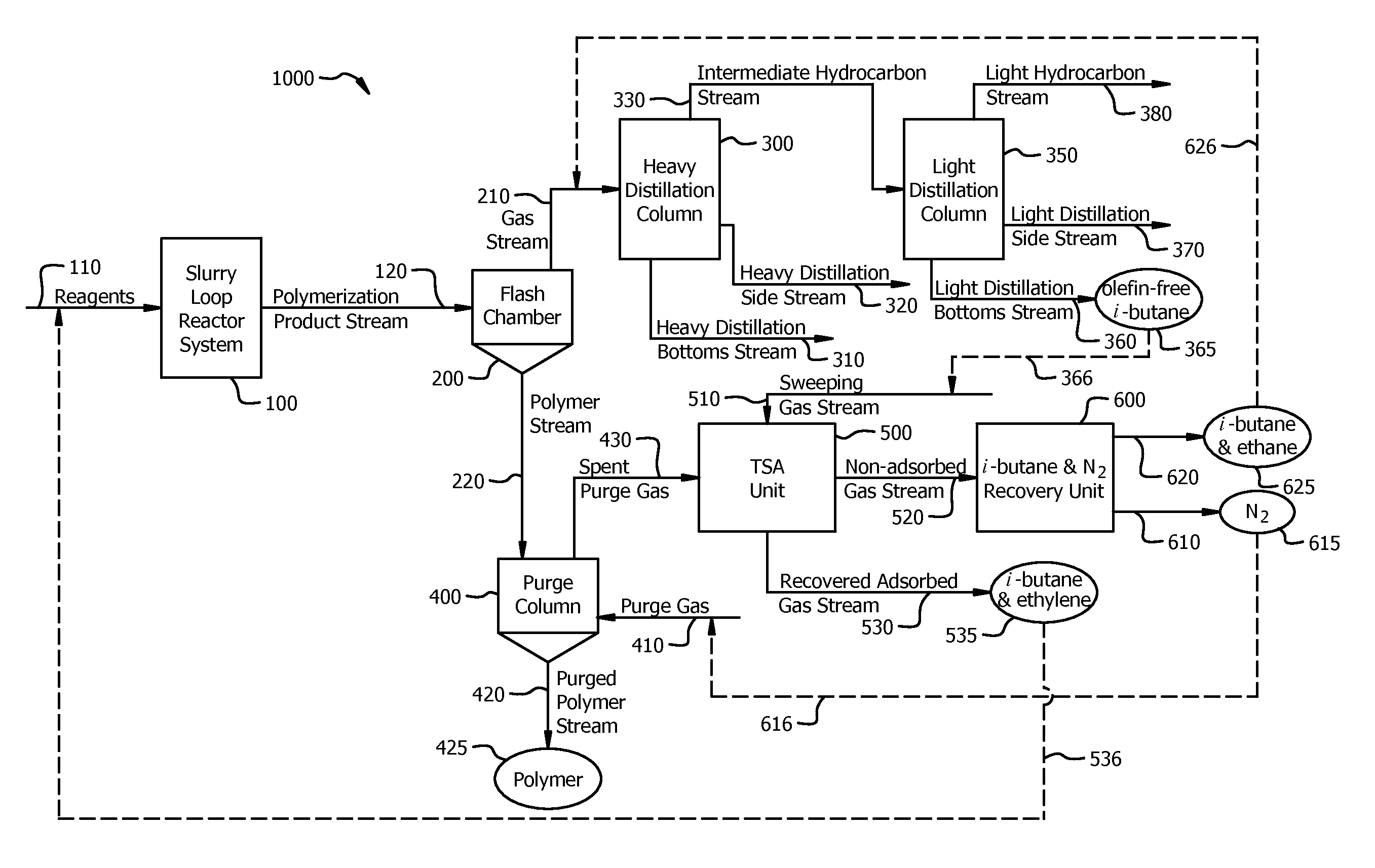
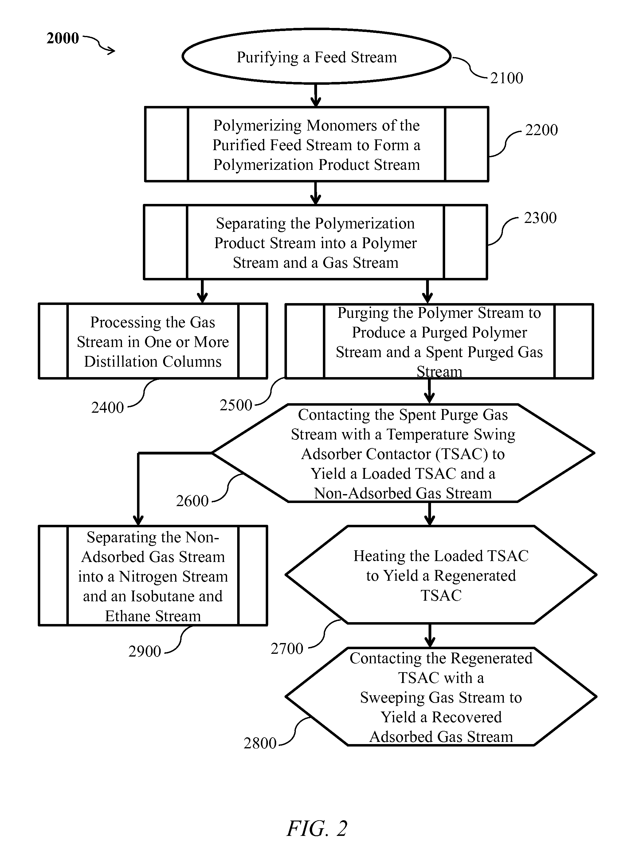
The patent describes a process for separating and purifying ethylene in a polyethylene production system. The process involves contacting a polymerization product stream with a purge gas to remove impurities and then using a temperature swing adsorber contactor (TSAC) to adsorb ethylene and ethane. The TSAC is then heated to a second temperature to desorb the adsorbed ethylene and ethane, resulting in a recovered adsorbed gas stream. The technical effect of this process is to provide a more efficient and effective method for separating and purifying ethylene in polyethylene production.

Problems solved by technology

As such, the energy costs associated with feedstock purification represent a significant proportion of the total cost for the production of such polymers.
Further, the infrastructure required for producing, maintaining, and recycling high purity feedstock is a significant portion of the associated capital cost.
In either case, conventional processes of recovering monomer (e.g., unreacted ethylene) have necessitated energetically unfavorable and expensive processes.

Method used


Image

  • Ethylene separation with temperature swing adsorption
  • Ethylene separation with temperature swing adsorption
  • Ethylene separation with temperature swing adsorption

Examples


first embodiment

[0200]A first embodiment which is a process for component separation in a polymer production system, comprising (a) separating a polymerization product stream into a gas stream and a polymer stream, wherein the polymer stream comprises polyethylene, ethylene and ethane; (b) contacting at least a portion of the polymer stream with a purge gas to yield a purged polymer stream and a spent purge gas stream, wherein the purged polymer stream comprises polyethylene, and wherein the spent purge gas comprises purge gas, ethylene, and ethane; (c) contacting at least a portion of the spent purge gas stream with a temperature swing adsorber contactor (TSAC) to yield a loaded TSAC and a non-adsorbed gas stream, wherein at least a portion of the ethylene is adsorbed by the TSAC at a first temperature to yield TSAC-adsorbed ethylene, wherein a portion of the ethane is adsorbed by the TSAC at the first temperature to yield TSAC-adsorbed ethane, and wherein the loaded TSAC comprises TSAC-adsorbed e...

fourth embodiment

[0223]A twenty-fourth embodiment which is the process of the twentieth embodiment wherein the TSAC further comprises a support.

[0224]A twenty-fifth embodiment which is the process of any of the twentieth through twenty-fourth embodiments wherein the hydrocarbon adsorber contacts at least a portion of the support, is distributed throughout the support, or combinations thereof.

[0225]A twenty-sixth embodiment which is the process of any of the twenty-fourth through twenty-fifth embodiments wherein the support comprises a film, a foil, a mesh, a fiber cloth, a fiber cloth, a woven fiber mesh, a woven wire mesh, a metallic woven wire mesh, a polymeric membrane, a surface treated material, a surface treated metal foil, a woven fiber cloth, or combinations thereof.

[0226]A twenty-seventh embodiment which is the process of any of the twenty-fourth through twenty-sixth embodiments wherein the support comprises a thermally conductive polymer.

[0227]A twenty-eighth embodiment which is the proces...

sixth embodiment

[0235]A thirty-sixth embodiment which is a process for component separation in a polymer production system, comprising (a) separating a polymerization product stream into a gas stream and a polymer stream, wherein the polymer stream comprises polyethylene, ethylene and ethane; (b) contacting at least a portion of the polymer stream with nitrogen to yield a purged polymer stream and a spent purge gas stream, wherein the purged polymer stream comprises polyethylene, and wherein the spent purge gas comprises nitrogen, ethylene, and ethane, wherein a pressure of the spent purge gas stream is from about 100 kPa to about 150 kPa, wherein ethylene is characterized by a partial pressure of less than about 10 kPa, and wherein ethane is characterized by a partial pressure of less than about 5 kPa; (c) contacting at least a portion of the spent purge gas stream with a temperature swing adsorber contactor (TSAC) comprising a 4 A zeolite and a plurality of hollow tubes at about 20° C. to yield a...


PUM

PropertyMeasurementUnit
Temperatureaaaaaaaaaa
Timeaaaaaaaaaa
Timeaaaaaaaaaa

Abstract

A process for component separation in a polymer production system, comprising (a) separating a polymerization product stream into a gas stream and a polymer stream, (b) contacting the polymer stream with a purge gas to yield a purged polymer and a spent purge gas comprising purge gas, ethylene, and ethane, (c) contacting the spent purge gas with a temperature swing adsorber contactor (TSAC) to yield a loaded TSAC, wherein at least a portion of the ethylene is adsorbed by the TSAC at a first temperature to yield TSAC-adsorbed ethylene, wherein a portion of the ethane is adsorbed by the TSAC at the first temperature to yield TSAC-adsorbed ethane, (d) heating the loaded TSAC to a second temperature to yield a regenerated TSAC, and (e) contacting the regenerated TSAC with a sweeping gas stream to yield a recovered adsorbed gas stream comprising sweeping gas, recovered ethylene and recovered ethane.

Description

TECHNICAL FIELD[0001]The present disclosure generally relates to the production of polyethylene. More specifically, this disclosure relates to a process for improving polyethylene production efficiency by recovering unreacted ethylene.BACKGROUND[0002]The production of polymers such as polyethylene from light gases requires a high purity feedstock of monomers and comonomers. Due to the small differences in boiling points between the light gases in such a feedstock, industrial production of a high purity feedstock can require the operation of multiple distillation columns, high pressures, and cryogenic temperatures. As such, the energy costs associated with feedstock purification represent a significant proportion of the total cost for the production of such polymers. Further, the infrastructure required for producing, maintaining, and recycling high purity feedstock is a significant portion of the associated capital cost.[0003]In order to offset some of the costs and maximize product...

Claims


Application Information

Patent Timeline
IPC IPC(8): C08F2/00B01D53/04C08F210/00C07C7/13C07C7/00C08F110/02
CPCC07C7/13B01D53/0462C07C7/005C08F110/02B01D2253/116B01D2253/108B01D2253/204B01D2257/7022B01D2256/24B01D53/0407B01D2253/102B01D2259/40043B01J8/085B01J8/087B01J19/00B01J2208/00212B01J2208/00274B01J2219/0004B01J2219/00837B01J2219/00842C07C7/12Y02P20/582C08F10/02C08F2/01C08F210/16C08F210/14C08F2/14C07C11/04
Inventor JI, LEICHANG, AI-FU
Owner CHEVRON PHILLIPS CHEMICAL CO LP
Learn More