CPP-type magnetoresistance effect element and magnetic disk device

a magnetoresistance effect and magnetic disk technology, applied in the field of cpp-type magnetoresistance effect elements and magnetic disk devices, can solve the problems of difficult to generate a strong exchange coupling between the two ferromagnetic layers, limited operation current, and reduced heat dissipation efficiency, so as to prevent deterioration, improve linear recording density, and ultra-high recording density

Active Publication Date: 2015-09-08
TDK CORPARATION
View PDF7 Cites 1 Cited by
  • Summary
  • Abstract
  • Description
  • Claims
  • Application Information

AI Technical Summary

Benefits of technology

[0016]In order to meet the demand for ultra-high recording density in recent years, the purpose of the present invention is to provide a magnetoresistive effect element, a thin film magnetic head that is provided with the magnetoresistive effect element, and a head gimbal assembly and a magnetic disk device that contain the thin film magnetic head, the magnetoresistive effect element allowing a linear recording density to be improved by adopting a structure in which the read gap (the gap between the upper and the lower shield layers) can be narrowed and also allowing a medium to be prevented from deteriorating by effectively inhibiting erroneous writing to the medium, demagnetization and degaussing of a recorded signal.
[0028]According to the present invention, in order to meet the demand for ultra-high recording density in recent years, a magnetoresistive effect element, a thin film magnetic head that is provided with the magnetoresistive effect element, and a head gimbal assembly and a magnetic disk device that contain the thin film magnetic head can be provided, the magnetoresistive effect element allowing a linear recording density to be improved by adopting a structure in which the read gap (the gap between the upper and the lower shield layers) can be narrowed and also allowing a medium to be prevented from deteriorating by preventing erroneous writing to the medium.

Problems solved by technology

There is a problem that heat dissipation efficiency decreases as the area decreases in a conventional structure and thus an operation current is limited from a point of view of reliability.
However, a disadvantage may occur in a TMR element, since an insulating film such as an aluminum oxide (AlOx) film or a magnesium oxide (MgO) film must be interposed between the two ferromagnetic layers in order to obtain a tunneling effect, it is difficult to generate a strong exchange coupling between the two ferromagnetic layers.
As a result, it is extremely difficult to have the magnetizations of the two ferromagnetic layers in an antiparallel state.
To increase the thickness of the permanent magnet HM and narrow the read gap will reduce gaps between the permanent magnet HM and an upper and a lower shield layers 71, 72 and a problem may occur that the bias magnetic field generated from the permanent magnet HM leaks to the upper and the lower shield layers 71, 72 so that the application of the bias magnetic field to the element becomes insufficient, and the resistance change of the element cannot be sufficiently detected.
However, a problem may also occur that there is a risk that the bias magnetic field from the permanent magnet HM may leak from the element, and due to the leakage magnetic field, a signal may be erroneously written to a medium, or a signal recorded in a medium may be demagnetized or degaussed.

Method used


Image

  • CPP-type magnetoresistance effect element and magnetic disk device
  • CPP-type magnetoresistance effect element and magnetic disk device
  • CPP-type magnetoresistance effect element and magnetic disk device

Examples


experimental example 1

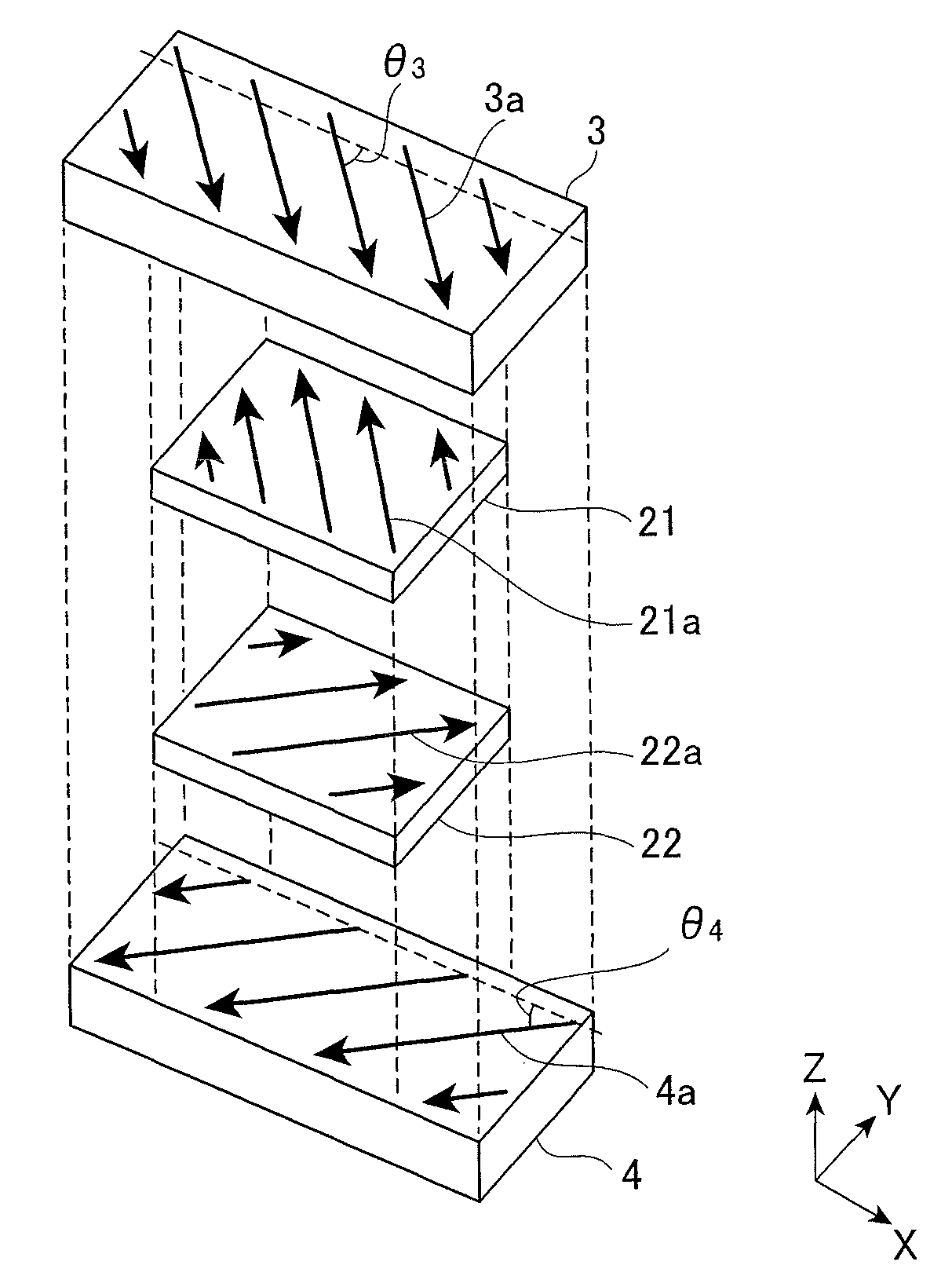
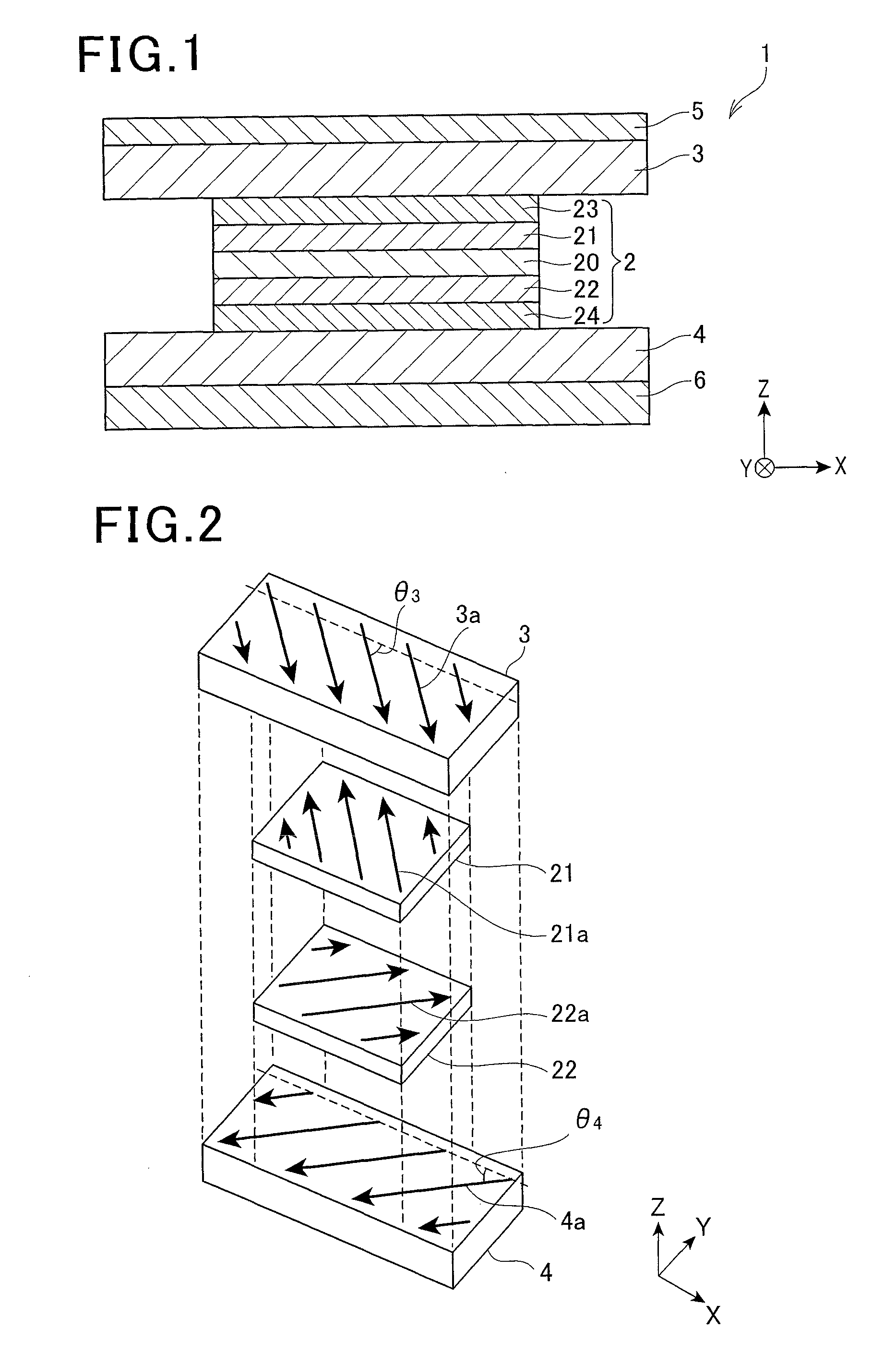
[0161]A magnetoresistive effect element (Example 1) having a configuration as illustrated in FIGS. 1, 2, 4A, 4B and 6 was fabricated.

[0162]That is, as illustrated in the following Table 1, on top of a second antiferromagnetic layer 6 that was made of IrMn, a lower shield layer 4 that was made of NiFe and had a thickness of 125 {acute over (Å)} is formed. On top of this lower shield layer 4, an MR part 2 that had a lamination configuration as illustrated in Table 1 was formed. The thickness of the second antiferromagnetic layer 6 was 100 {acute over (Å)} so that the blocking temperature (Tb6) of the second antiferromagnetic layer 6 was 270° C.

[0163]Then, with respect to the multilayer body that included the second antiferromagnetic layer 6, the lower shield layer 4 and the MR part 2, a first annealing treatment (see FIG. 11A) was performed in which, while a magnetic field (3 kOe) was applied in a direction of a predetermined angle θ4, heating was performed at a temperature (280° C.) ...

experimental example 2

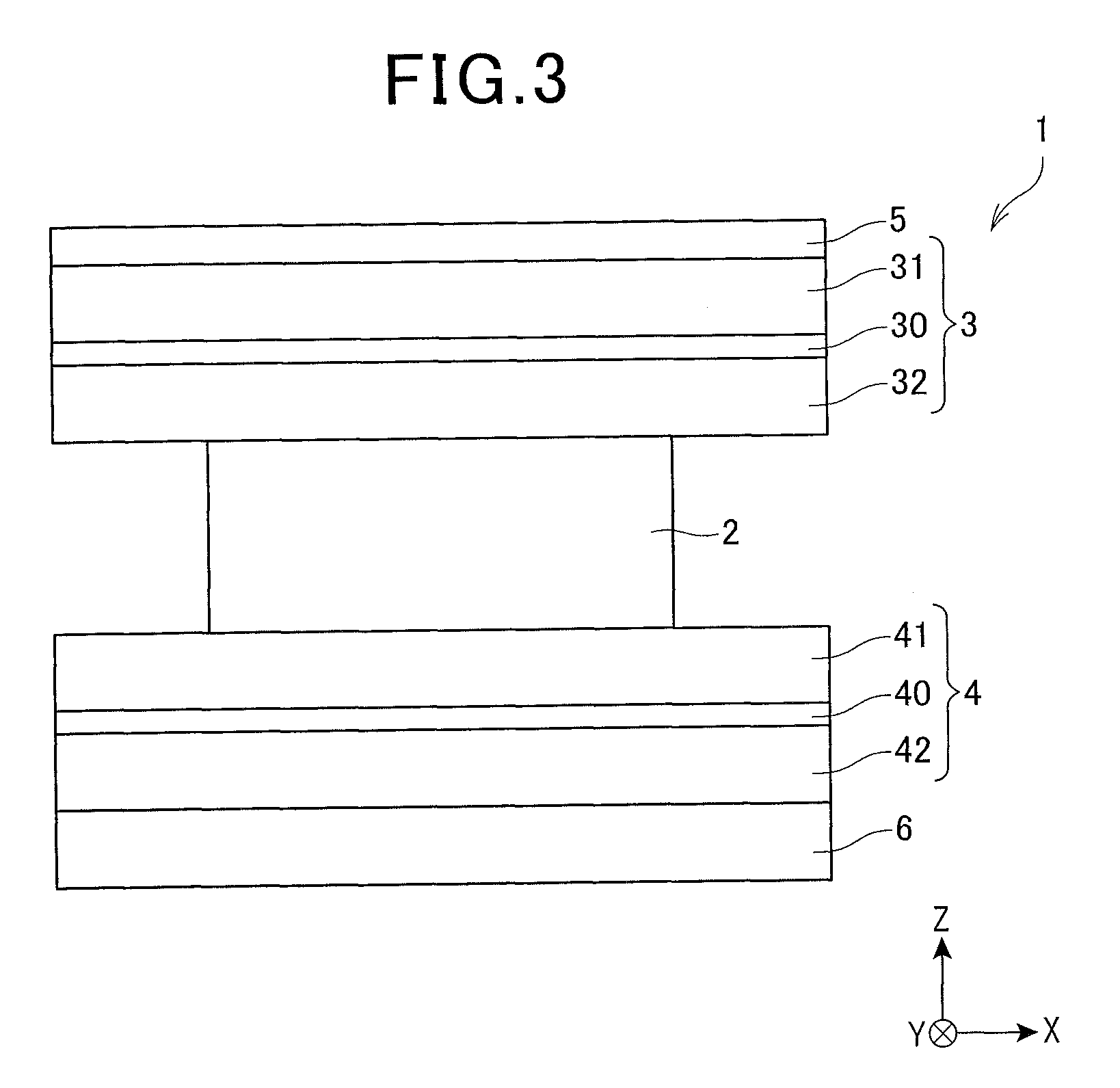
[0169]A magnetoresistive effect element (Example 2) having a configuration as illustrated in FIGS. 2, 3, 4A, 4B and 6 was fabricated.

[0170]That is, as illustrated in the following Table 2, on top of a second antiferromagnetic layer 6 that is made of IrMn, a lower shield layer 4 was formed in which a second lower shield layer 42 that was made of NiFe and had a thickness of 125 {acute over (Å)}, a lower nonmagnetic layer 40 that was made of Ru and a first lower shield layer 41 that was made of NiFe and has a thickness of 125 {acute over (Å)} were laminated in this order. On top of the lower shield layer 4 (on top of the first lower shield layer 41), an MR part 2 that had a lamination configuration as illustrated in Table 2 was formed. The thickness of the second antiferromagnetic layer 6 was 100 {acute over (Å)} so that the blocking temperature (Tb6) of the second antiferromagnetic layer 6 was 270° C.

[0171]Then, with respect to the multilayer body that included the second antiferromag...

experimental example 3

[0177]A spin stand on which a magnetic head was mounted was used to evaluate recording and reproducing characteristics (R / W characteristics). As the magnetic head, a combination of a single magnetic pole head that had a recording track width of 60 nm and a MR head that contained the magnetoresistive effect element of the above Example 1 and Example 2 and had a reproducing track width of 40 nm was used.

[0178]Measurement wasperformed at a condition that a disk was rotated at 5400 rpm at a constant position of a radius position of 22.3 mm.

[0179]As a medium SNR, a value of a signal-to-noise ratio (S / Nm) of a differential waveform after passing through a differentiating circuit was evaluated. Here, S was an output at 299 kfci, and Nm was a RMS (Root Mean Square) value at 793 kfci. Further, a track average signal amplitude (TAA: Track Average Amplitude) at 299 kfci was evaluated.

[0180]The results are illustrated in Table 3.

[0181]

TABLE 3TAA (mV)S / Nm (dB)Example 12.714.7Example 22.616.3

[018...


PUM

PropertyMeasurementUnit
total thicknessaaaaaaaaaa
thicknessaaaaaaaaaa
thicknessaaaaaaaaaa

Abstract

A magnetoresistive effect element that prevents a recording medium from deteriorating by effectively inhibiting erroneous writing to a medium or the like includes a magnetoresistive effect part, and an upper shield layer and a lower shield layer that are laminated and formed in a manner sandwiching the magnetoresistive effect part from above and below, and is in a current perpendicular to plane (CPP) structure in which a sense current is applied in a lamination direction. The magnetoresistive effect part includes a nonmagnetic intermediate layer, and a first ferromagnetic layer and a second ferromagnetic layer that sandwich the nonmagnetic intermediate layer from above and below, the upper shield layer and the lower shield layer have inclined magnetization structures in which magnetizations of them are respectively inclined with respect to a track width direction, the magnetizations of the upper shield layer and the lower shield layer are mutually substantially orthogonal, the first ferromagnetic layer is indirectly magnetically coupled with the upper shield layer via a first exchange coupling function gap layer that is positioned between the first ferromagnetic layer and the upper shield layer, and the second ferromagnetic layer is indirectly magnetically coupled with the lower shield layer via a second exchange coupling function gap layer that is positioned between the second ferromagnetic layer and the lower shield layer.

Description

BACKGROUND OF THE INVENTION[0001]1. Field of the Invention[0002]The present invention relates to a magnetoresistive effect element for reading magnetic field intensity of a magnetic recording medium and the like as a signal, a thin film magnetic head that is provided with the magnetoresistive effect element, and a head gimbal assembly and a magnetic disk device that contain the thin film magnetic head.[0003]2. Description of the Related Art[0004]In recent years, along with the advancement of high recording density of a hard disk drive (HDD), further improvement is demanded in the performance of a thin film magnetic head. As a thin film magnetic head, a composite type thin film magnetic head is widely used having a structure in which a reproducing head having a read-only magnetoresistive effect element (MR element) and a recording head having a write-only induction-type magnetic transducer element are laminated.[0005]Currently, as a reproducing head, a magnetoresistive effect element...

Claims


Application Information

Patent Timeline
Patent Type & Authority Patents(United States)
IPC IPC(8): G11B5/39H01L43/08G01R33/09
CPCG11B5/3912G01R33/093G01R33/098G11B5/3906G11B5/398G11B5/3932H01L43/08H10N50/10
Inventor MACHITA, TAKAHIKODEGAWA, NAOMICHIYAMANE, TAKEKAZUYANAGISAWA, TAKUMIMIURA, SATOSHIHAMAMOTO, KENTAOTA, MINORUMAKINO, KENZOKAWASAKI, SHOHEI
Owner TDK CORPARATION
Why Eureka
Try Eureka