Duobinary voltage-mode transmitter

a transmitter and voltage mode technology, applied in the field of communication systems, can solve the problems of vm power and room to improve, and achieve the effect of improving impedance and reducing average power consumption

Active Publication Date: 2015-09-22
NCKU RES & DEV FOUND +1
View PDF6 Cites 10 Cited by
  • Summary
  • Abstract
  • Description
  • Claims
  • Application Information

AI Technical Summary

Benefits of technology

[0008]In view of the foregoing, it is an object of the embodiment of the present invention to provide a duobinary voltage-mode (VM) transmitter in which a drive

Problems solved by technology

However, there is still some room to improve regarding power consumption.
. . ” According to the disclosu

Method used


Image

  • Duobinary voltage-mode transmitter
  • Duobinary voltage-mode transmitter
  • Duobinary voltage-mode transmitter

Examples


Embodiment Construction

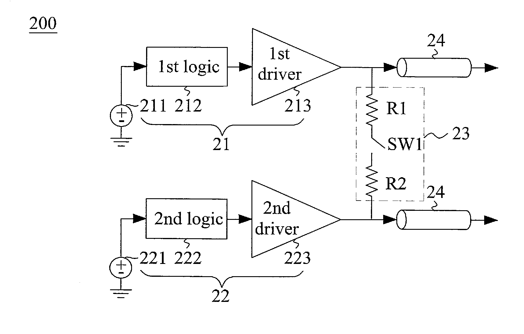
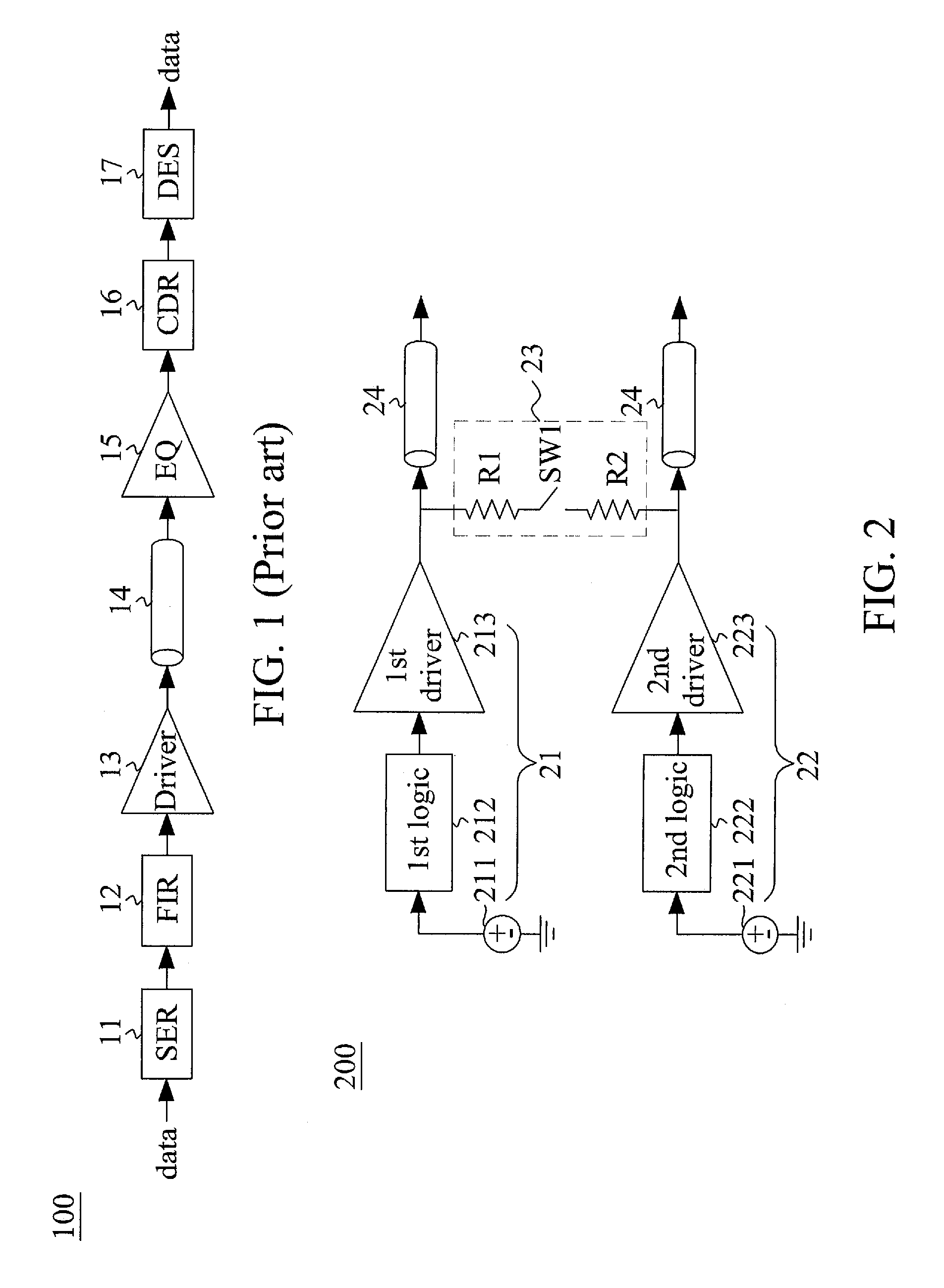
[0020]FIG. 2 shows a block diagram illustrated of a duobinary voltage-mode (VM) transmitter (transmitter hereinafter) 200 according to one embodiment of the present invention. The transmitter 200 of the embodiment includes two branches—a first branch 21 and a second branch 22. In the first branch 21, a first non-return-to-zero (NRZ) generator 211 generates a NRZ signal conforming to a 2-level NRZ code format, that is, a binary code in which, for example, “1” is represented by a positive voltage and “0” is represented by a negative voltage (or ground), with no other neutral or rest condition. Similarly, in the second branch 22, a second NRZ generator 221 generates a NRZ signal (conforming to the 2-level NRZ code format) that is complement to the generated NRZ signal from the first NRZ generator 211.

[0021]The first branch 21 includes a first logic circuit 212 coupled to receive the NRZ signals generated from the first NRZ generator 211, and configured to detect transition between the ...


PUM


Abstract

A duobinary voltage-mode transmitter comprises a first branch including a first logic circuit and a first driver, and a second branch including a second logic circuit and a second driver. When a transition occurs between NRZ signals, two ends of a first match circuit are electrically coupled between the output nodes of the first driver and the second driver, respectively, and the first driver and the second driver are turned off.

Description

BACKGROUND OF THE INVENTION[0001]1. Field of the Invention[0002]The present invention generally relates to a communication system, and more particularly to a duobinary voltage-mode (VM) transmitter.[0003]2. Description of Related Art[0004]FIG. 1 shows a block diagram of a wireline communication system 100 for transmitting and receiving data. Data are converted to a serial data stream by a serializer (SER) 11 to facilitate transmission over a single or a pair of differential lines. Transmit equalization is performed by a finite-impulse-response (FIR) filter 12, followed by a driver 13. Data are transmitted over a channel 14 such as a single or a pair of differential lines, and is received and processed by an equalizer (EQ) 15 to reduce intersymbol interference (ISI). The received data stream is then processed by a clock and data recovery (CDR) 16, followed by a deserializer (DES) 17 which converts the data stream into a parallel data format.[0005]Power consumption and impedance match...

Claims


Application Information

Patent Timeline
IPC IPC(8): H04L25/34H04L25/49H04B1/04H04L12/12
CPCH04B1/04H04L12/12Y02D30/50
Inventor CHANG, SOON-JYHGOH, JIH-RENHUANG, CHUNG-MING
Owner NCKU RES & DEV FOUND
Why Eureka
Try Eureka