Method of heating a preform, a driving arrangement, a preform heating system and a computer program

a preform and driving arrangement technology, applied in the field of heating a preform, can solve the problems of limited energy efficiency, poor energy efficiency, and the inability to effectively direct or focus radiation emitted by halogen lamps, and achieve the effect of reducing the number of halogen lamps

Inactive Publication Date: 2015-09-29
KONINK PHILIPS ELECTRONICS NV
View PDF19 Cites 1 Cited by
  • Summary
  • Abstract
  • Description
  • Claims
  • Application Information

AI Technical Summary

Benefits of technology

[0004]Therefore, it is an object of the invention to provide a more economical and effective preform heating process which avoids the problems mentioned above.
[0012]The ‘resolution’ of the effective absorption coefficient may depend to some extent on the capabilities of the laser radiation sources available, and how well these can be matched to the absorption coefficients of the material being heated. Obviously, when using a laser radiation source that comprises many differently tuned individual laser radiation sources, radiation can be generated at wavelengths resulting in an appropriate absorption in the material, so that the desired effective absorption coefficient αeff can be reproduced to a high degree of accuracy. However, even in systems with only a limited number of available wavelengths, the degree of freedom offered by the weighting factors may be put to good effect to obtain a close approximation of the desired value of the effective absorption coefficient αeff.
[0015]Therefore, the effective absorption coefficient (and further parameters) may preferably be chosen such that the energy absorption density is essentially uniform throughout the body of the preform. This allows a more energy-efficient heating process compared to prior art approaches, in which an excess of infrared energy is radiated in the direction of the preform but wasted to a large extent. Also, using the method according to the invention, a local overheating in regions of the preform is avoided, so that the inefficient and costly cooling required by prior art approaches is not needed.
[0030]Use of a refractive element located in the preform cavity can effectively distribute the laser radiation energy. Depending on the preform material, preform geometry, and choice of laser radiation source, however, it may be desirable to ‘dispose’ of some excess portion of the laser radiation. Therefore, in a further preferred embodiment of the invention, the temperature of the inner region of the preform can be regulated by means of a thermal absorber positioned in a cavity of the preform, which thermal absorber absorbs a portion of the laser radiation energy. In this way, the excess energy is not simply redirected to another region of the preform, but can be partially or completely ‘removed’. The material of the absorber can be chosen on the basis of its absorptive properties, for example to absorb laser radiation of all wavelengths used, or some or most of the wavelength used. The thermal absorber can be a solid, a liquid, or any suitable state. For example, the preforms can be suspended with their open ends facing upward on their path through the oven, and the thermal absorber can simply be water poured into the cavity and later poured out again before the preform is shaped by blow-moulding.

Problems solved by technology

The infrared heating technique, while technically well-developed, has the drawback of limited energy efficiency.
One reason for the poor energy efficiency is that the radiation emitted by the halogen lamps cannot effectively be directed or focused.
The main reason, however, is the poor matching of the emission spectrum of the halogen lamps to the absorption spectrum of the preform material, which results in absorption of energy in inappropriate regions of the preform, for example in its outer surface.
This results in higher temperatures in some regions of the preform wall, while other regions are insufficiently heated.
For example the outside surface of the preform may become very hot while the inside surface is insufficiently heated.
Such temperature gradients or hot spots make it difficult to ensure an even quality of the subsequent blow-moulding stage, and may even result in damage to the outer surface of the preform.
Therefore, some prior art processes even resort to an additional cooling of the preforms during the heating-process (for example by forced-air cooling); a measure which is obviously costly and inefficient from the point of view of energy consumption, and therefore undesirable.
However, including these phases into the heating process means that the total process time is lengthened, thereby increasing the overall cost of the preform heating process.

Method used


Image

  • Method of heating a preform, a driving arrangement, a preform heating system and a computer program
  • Method of heating a preform, a driving arrangement, a preform heating system and a computer program
  • Method of heating a preform, a driving arrangement, a preform heating system and a computer program

Examples


Embodiment Construction

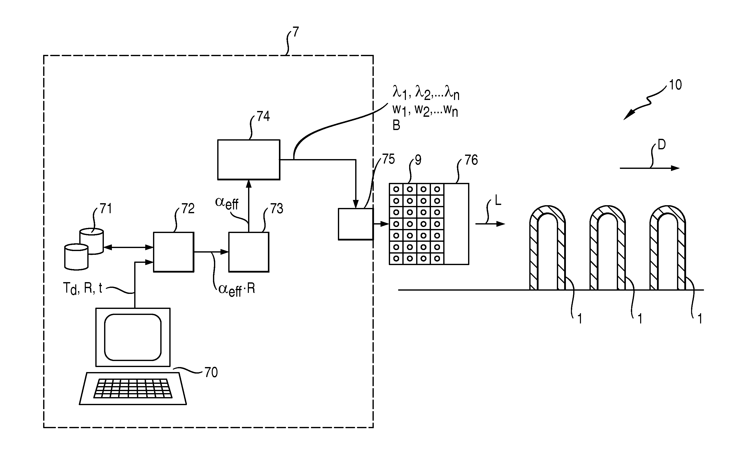
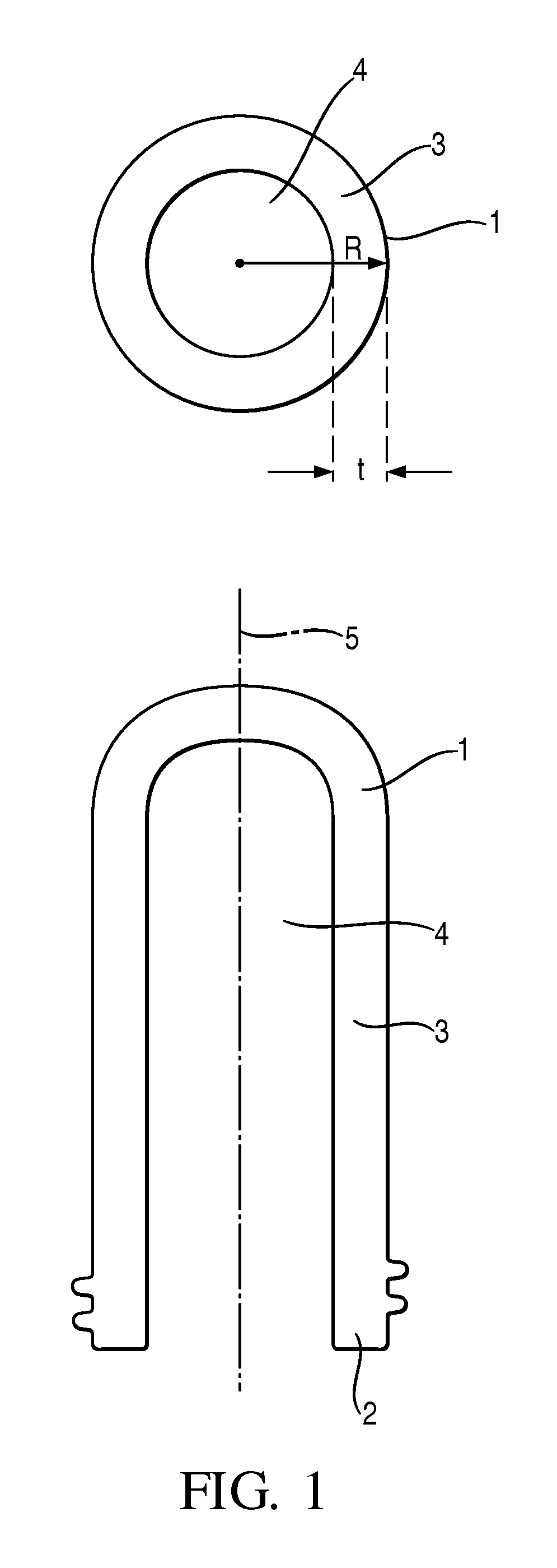
[0052]FIG. 1 shows a transverse cross-section and a longitudinal cross-section through the body 3 of a preform 1. Such a preform 1, intended for use as a beverage container or bottle, already features a threaded neck 2, which, contrary to the body 3 of the preform 1, is usually not subjected to any heating and thus remains largely unaffected by the subsequent blow-moulding of the heated preform body 3. The cavity 4 of the preform 1 can be used to fixate the preform 1 during its path through the oven or furnace, as a bottle-blowing apparatus is usually termed, for example by a rod or pin upon which the preform is placed. While being heated, the preform may be rotated about its longitudinal axis 5. When heated in the oven, the body 3 of the preform 1 becomes hot and softens as a result, so that, in a subsequent treatment step, air forced into the cavity 4 of the preform 1 under a certain pressure causes the preform body 3 to expand. Suitable shaping means external to the preform 1 may...


PUM

PropertyMeasurementUnit
temperatureaaaaaaaaaa
wavelengthsaaaaaaaaaa

Abstract

The invention describes a method of heating a preform (1) characterized by a radius (R), a material thickness (t), and a material absorption spectrum, which method comprises the steps of selecting, depending on a desired temperature profile, a desired effective absorption coefficient for the preform (1) on the basis of the preform radius (R) and material thickness (t); generating a laser radiation beam (L) comprising radiation with a wavelength spectrum compiled on the basis of absorption coefficients of the absorption spectrum to satisfy the effective absorption coefficient and directing the laser radiation beam (L) at the preform (1) to heat the preform (1). The invention further describes a driving arrangement (7) for controlling a laser radiation generating unit (9) of a preform heating system (10), a preform heating system (10), and a computer program.

Description

FIELD OF THE INVENTION[0001]The invention describes a method of heating a preform. The invention also describes a driving arrangement, a preform heating system and a computer program for heating a preform.BACKGROUND OF THE INVENTION[0002]Nowadays, the majority of beverage containers are lightweight plastic bottles of a material such as PET (polyethylene terephthalate), manufactured in a two-step process. In a first step, so-called hollow “preforms” are created from the raw material, e.g. by a slow, high-temperature extrusion process. In a second step the ‘walls’ of these hollow preforms are heated again—this time to a temperature below their re-crystallization point, i.e. below about 130° C.—and then formed into the desired bottle-shapes via blow-moulding.[0003]In most state of the art preform heating ovens, this heating is carried out using halogen lamps, for which a significant portion of the broad emission spectrum lies in the infrared region. During the heating process, heat ene...

Claims


Application Information

Patent Timeline
Patent Type & Authority Patents(United States)
IPC IPC(8): H05B7/18H05B6/00B29C49/64B29C35/08B29K67/00
CPCB29C49/6454B29C2035/0838B29K2067/00
Inventor POLLMANN-RETSCH, JENSSTROESSER, MARTINPEKARSKI, PAVEL
Owner KONINK PHILIPS ELECTRONICS NV
Why Eureka
Try Eureka